Using the Water Balance Tool
The water balance utility is a post-processing tool for generating water balance summaries from MIKE SHE simulations. Water balance output can include area normalized flows (storage depths), storage changes, and model errors for individual model components (e.g., unsaturated zone, evapotranspiration, etc.).
A water balance can be generated at a variety of spatial and temporal scales and in a number of different formats, including dfs0 time series files, dfs2 grid series files, and ASCII text output suitable for importing to Microsoft Excel.
You can also automatically create a picture that visualizes the interrelationships between the various water balance components (see Figure 6.1).
The water balance utility can be run from within the MIKE Zero interface or from a DOS batch file. The batch functionality allows you to calculate water balances automatically after a MIKE SHE simulation that is also run in batch mode. Alternatively, you can also calculate water balances as part of an AUTOCAL simulation and use the results as part of an objective function.
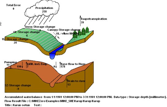
Figure 6.1 Graphical water balance output example
1. Creating a Water Balance
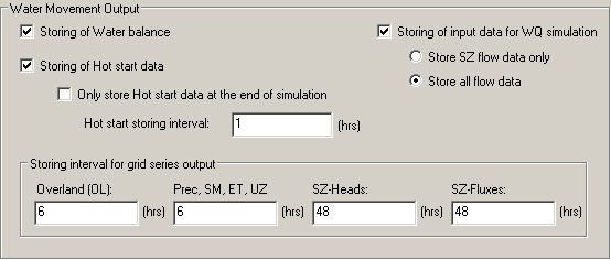
Before you can create a water balance for a MIKE SHE WM simulation, you must have saved the water balance data during the simulation. Saving of the water balance data is specified in the Storing of Results dialogue. If you have forgotten to save the water balance data, then you will need to rerun your simulation.
Note
The available time step resolution of the water balance will be the same as the Storing Interval for Grid Series Output. If the storing intervals are different, then it will be the largest Storing Interval.
After you have run your WM simulation, creating and running a water balance in MIKE SHE is quite simple, following these steps
- Create a new water balance document,
- Extract the water balance data
- Specify your water balance, and
- Calculate and View the Water Balance.
Create a new water balance document
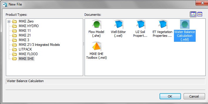
The new water balance document is created by selecting the File/New item in the top menu, or clicking on the New icon in the top menu bar. In the dialogue that appears, select MIKE SHE and Water Balance Calculations in the right hand box, as shown below.
Extract the water balance data
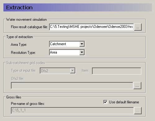
To extract the water balance data, specify the MIKE SHE simulation by selecting the simulation catalogue file (.sheres file), then specify the area of your model that you want the water balance for, and, finally, extract the MIKE SHE water balance data from the results files.
Once you have created a new water balance document, the first tab is as shown below.
Flow result catalogue file
A MIKE SHE simulation generates various output files depending on the options and engines selected for the MIKE SHE simulation. The .sheres file is a catalogue of all the various output files generated by the current MIKE SHE run. When you select the .sheres file, you are not specifying the particular output, but actually just a set of pointers to all the output files.
The extraction process reads all of the output files and makes itself ready to produce specific water balances. In the extraction dialogue, you specify the .sheres file for the simulation that you wish to calculate the water balance for. The .sheres file is located in the same directory as your results.
Note
Although, this is an ASCII file, you should be careful not to make any changes in the file, or you may have to re-run your simulation.
Type of Extraction
You can choose to calculate the water balance on the entire model domain or in just a part of the domain. By default the calculation is for the entire domain, or catchment. If you choose the subcatchment area type, they you will be able to use a dfs2 integer grid code file to define the areas that you want individual water balances for.
If you use an area resolution, then the water balance will be a summary water balance for either the entire catchment or the sub-areas that you define.
If you use a single-cell resolution, you will be able to generate dfs2 maps of the water balance.
Sub-catchment grid codes
The subcatchment integer grid code file is only used if you have selected the sub-catchment water balance type. You can specify a delete value to exclude areas from the water balance. The grid spacing and dimensions in this dfs2 file do not have to match the model grid exactly. However, the sub-catchment grid must be both coarser than and aligned with the original grid.
You can also specify a polygon shape file to define the sub-catchment areas. The shape file may contain multiple polygon, with the same or different codes. Further, the shape file length units do not have to be the same as the model length units (e.g. feet vs. meters).
Gross files
The pre-processor extracts the water balance data from the standard MIKE SHE output files and saves the data in a set of “gross” files. The file names of the gross files is built up from the project name and prefix specified here. The default value is normally fine.
Run the extraction
To run the extraction, you simply have to click on the Run Extraction icon,  , or the Run/Extraction top menu item.
Specify your water balance
After you have extracted the water balance data from the MIKE SHE results files, then you can switch to the post-processing tab. Here you can create any number of individual water balances by simply clicking on the Add item icon and specifying the water balance parameters in the parameter dialogue.
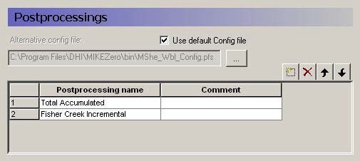
A single Postprocessing item is created by default when the water balance file is created. The default Postprocessing name can be change to a more appropriate name. Postprocessing items that are no longer needed can be deleted using the Delete button.
Use default Config file
Unchecking the Use default Config file checkbox, allows you to specify the location of a custom water balance Config file. Development of custom water balance configuration files is described in detail in Making Custom Water Balances.
For each item in the Postprocessing list above, a new item will be added to the data tree. If you expand the data tree, each will have the following dialogue.
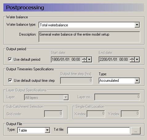
Water Balance
Multiple post-processing can be run on each water balance extraction. More detail on the types of available water balances data is discussed in the Available Water Balance Items section. In brief, the available types include
- The total water balance of the entire model catchment or sub-catchments in an ASCII table, a dfs0 file, a dfs2 map file,
- A graphical cartoon (“Chart” type) of the total water balance (such as Figure 6.1),
- Model errors for each hydrologic component (overland, unsaturated zone, etc.) in an ASCII table, a dfs0 file, or a dfs2 map file (also by layer),
- The snow melt and canopy/interception water balance in an ASCII table, or a dfs0 file,
- An abbreviated or detailed water balance for overland or unsaturated flow in an ASCII table, or a dfs0 file, and
- An abbreviated or detailed water balance by layer for saturated flow in an ASCII table, or a dfs0 file.
Output Period
An output period different from the total simulation period can be specified by unchecking Use default period and setting the Start date and End date to the period of interest
Output Time Series Specification
Incremental or Accumulated water balances can be calculated. An incremental water balance is calculated (summed) for each output time step in the Output period. An accumulated water balance each output time step is accumulated over the Output period
Layer Output Specifications
If you are using water balance types that calculate data on a layer basis, you can specify whether you want All layers or just the Specified layer, where you also must specify a layer number.
Sub-catchment Selection
If you extracted sub-catchment data from the WM results, then you must specify a subcatchment number or the name of the polygon for which you want the water balance for. The combo-box contains a list of valid ID numbers or polygon names.
Single Cell Location
If you extracted the WM data by cell and you are not creating a map output, you have to specify a cell location for which you want a water balance.
Output File
If you are creating a table or time series water balance, then you can write the output to either a dfs0 file or to a tab-delimited ASCII file for import to MS Excel, or other post-processing tool. If you are creating a map, then the output will be to a dfs2 file, with the same grid dimensions and spacing as the model grid. If you are creating a chart, then the output will be written to an ASCII file, with a special format for creating the chart graphic.
Run the Post Processing
To run the post processing, you have two choices. You can click on the Run Selected Post-Processing icon,  , which runs only the current post-processing item. Or, you can click on the Run All Post-Processing icon,
  , which runs all of the post-processing items in the list. These two options are also available in the Run top menu.
Calculate and View the Water Balance
The data tree for the results tab lists all of the calculated water balances. The dialogue for each item, includes the file name and an Open button that will open an editor for the file. For ASCII output, this will be your default ASCII editor - usually Notepad. For dfs0 and dfs2 files, the DHI Time Series Editor
or Grid Editor will be opened. For the chart output, the graphic will be displayed by the program WblChart.
Units for the water balance
The values in the water balance are in the EUM unit type Storage Depth. This normalization allows water balances for different models or model areas to be more easily compared. The Storage Depth values can be converted to volume by multiplying by the internal model area. The number of internal model cells can be found in the _WM_PRINT.LOG file. Thus, the internal area is the number of cells times the area per cell. If you have calculated a water balance on a sub-area, the volumes must be calculated based on the number of internal cells in the sub-area.
The default units are [mm], but this can be changed to any length unit (e.g. inches) by changing the EUM unit of the variable Storage Depth.
2. Display and auto-run of water balances in the MIKE SHE Results tab
It's possible to add one or more water balances to the Results tab of MIKE SHE, enabling viewing water balance results in the same way as in the Result tab of the Water Balance tool. In addition, if a water balance has been added to the MIKE SHE Results tab, then the water balance is recalculated automatically after each MIKE SHE simulation.
Details about adding water balances to the MIKE SHE Results tab are provided in Water Balances.
3. Calculating Water Balances in Batch Mode
Like most DHI software, the water balance utility can be run in batch mode. This is useful if you want to run the water balance utility:
- immediately after a simulation that was also run in batch mode, or
- without using the water balance utility graphical user interface.
The water balance utility stores all of its information in a .wbl file. The .wbl file is an ASCII file that can be edited with Notepad or other text editor, but the format of the water balance file must be preserved. For more information on editing the .wbl file and creating custom water balances, see Making Custom Water Balances.
The executables for the water balance utility are found in the installation directory (..\bin\x64). There are three executables.
To perform the water balance extraction use:
MSHE_Wbl_Ex.exe xxx.wbl
where xxx.wbl is the water balance .wbl input file. To run an individual water balance use:
MSHE_Wbl_Post.exe xxx.wbl num
where num is the number of the post-processing water balance item that you want to run. To display the chart water balance output use:
MSHE_WblChart.exe xxx.txt
where xxx.txt is the output text file for the water balance chart defined in the post-processor item.
The number in the Postprocessing command must be consistent with the water balance utility file (i.e., the number cannot be greater than the number of Postprocessing items in the file). Otherwise, the program will terminate with an error. The Postprocessing step cannot be executed before an Extraction step but only one Extraction step needs to be run for a single water balance utility file.
To run the water balance utility in batch mode, the .wbl file must be created prior to executing the water balance and all file names in the .wbl file need to be valid.
If during calibration the same MIKE SHE file name is used for each simulation then the same .wbl file can be used for all calibration runs. If the MIKE SHE simulation to be evaluated is different from the MIKE SHE simulation used to set up the water balance file, you will have to edit the .wbl file.
To run the Extraction and Postprocessing steps in batch mode, the PATH statement needs to include the directory where MIKE SHE was installed. For the 2025 Release, the default directory is
C:\Program Files(x86)\DHI\MIKE Zero\2025\bin\x64
The batch file can contain Extraction and Postprocessing steps from multiple water balance utility files.
An example is shown below of a batch file that generates water balance data for three postprocessing steps, using a water balance utility file named WaterConservationAreas.WBL.
rem

MSHE_Wbl_Ex.exe WaterConservationAreas.WBL

MSHE_Wbl_Post.exe WaterConservationAreas.WBL 1

MSHE_Wbl_Post.exe WaterConservationAreas.WBL 2

MSHE_Wbl_Post.exe WaterConservationAreas.WBL 3
4. Available Water Balance Items
The .shres file contains a list of all of the simulation output files generated during the WM or WQ simulation. When you use the water balance extraction utility, all of these files are processed and a special set of water balance files are created - the .wblgross files. One file is created for each of the water balance components:
- Snowmelt and precipitation - projectname_sm.wblgross
- Canopy interception - projectname_ci.wblgross
- Ponded surface water - projectname_ol.wblgross
- Unsaturated zone - projectname_uz.wblgross
- Saturated zone - projectname_sz.wblgross
The contents of each of these files can be output using the “Detailed” water balances. All of the items in these files are listed and described in the following tables:
- Table 6.1 SM - Precipitation and snowmelt items
- Table 6.2 CI - Canopy interception water balance items
- Table 6.3 OL - Overland flow items
- Table 6.4 UZ - Unsaturated Zone items
- Table 6.5 SZ - Saturated Zone - all layers
- Table 6.6 SZ - Saturated Zone - specified by layers
- Table 6.7 SZ - Saturated Zone - Linear Reservoir all layers
The water balance utility is a very flexible tool that allows you to modify existing Water balance types or create custom Water balance types to suit your needs. The water balance calculations use a water balance Configuration) file to define Water balance types using the available water balance items and a macro language to control program execution.
To modify existing or custom Water balance types you must understand the available items and what data they contain.
Sign Conventions
MIKE SHE uses a sign convention that is positive in the positive coordinate direction. In other words, water flowing upward in the model is a positive flow in MIKE SHE. Likewise, flow in the direction of increasing x or y is also positive. Boundary flows and other flows that do not have a direction are positive outwards.
However, the water balance utility uses a control volume sign convention, such that all inflows are negative and all outflows are positive. This can cause confusion when calculating a water balance. For example, a vertical downward flow through the unsaturated zone will always be a negative result in MIKE SHE. In the water balance control volume, a downward flow into the unsaturated zone will be a positive outflow in the water balance for ponded water, but a negative inflow into the unsaturated zone water balance.
The sign convention for the water balance error of each storage is such that an increasing storage is positive. Thus, a positive water balance error means that the change in storage plus the total outflows is greater than the total inflows. In other words, the error is positive if your model is creating water.
Snow Storage
The snow storage items include all of the water balance items related to rainfall and the conversion to and from snow.
The items listed in Table 6.1 are those found in the “Snow Melt component - detailed” water balance output in the water balance configuration file:
[WblTypeDefinition]

Name = 'SM_DETAIL'

DisplayName = 'Snow Melt component - detailed' Description = 'Detailed Snow Melt component water balance' NoGroups = 11

Group = 'Precip and Irr -\> Snow(sm.qprecandirrtosnow)' Group = 'AirTemp Freezing(sm.qfreezing)'

Group = 'AirTemp Melting(sm.qthawing)' Group = 'Radiation Melting(sm.qradmelting)' Group = 'Rain Melting(sm.qrainmelting)' Group = 'Snow -\> OL(sm.qsnowtool)'

Group = 'Snow Evap(sm.qesnow)'

Group = 'Dry Snow Stor.Change(sm.dsnowsto-sm.dwetsnowsto)' Group = 'Wet Snow Stor.Change(sm.dwetsnowsto)'

Group = 'Total Snow Stor.Change(sm.dsnowsto)'

Group = 'Error(sm.smwblerr)' EndSect // WblTypeDefinition
The sign convention is such that precipitation is negative (inflow) and melting is positive (outflow). All of the noted items together should add to zero. The freezing and thawing items are not included in the error term because they are internal transfers of water between dry snow and wet snow storages.
The snow storage items are found in the projectname_sm.wblgross file. This file also contains the terms sm.qP, sm.qPad, and sm.PIrrSprinkler, which are not included in the detailed water balance output because they are included in the term sm.qPrecAndIrrToSnow.
Table 6.1 SM - Precipitation and snowmelt items
| Item | Description | Sign Convention in the Water balance | Included in Wbl Error |
|---|---|---|---|
| sm.qPrecAndIrrToSnow | Precipitation plus irrigation added to snow storage when the air temperature is below the freezing temperature | Inflow - negative | yes |
| sm.qFreezing | Amount of wet snow converted to dry snow due to freezing | Negative | no |
| sm.qThawing | Amount of water removed from dry snow storage due to temperature melting | Positive when melting occurs | no |
| sm.qRadMelting | Amount of water removed from dry snow storage due to radiation melting | Positive when melting occurs | no |
| sm.qRainMelting | Amount of water removed from dry snow storage due to melting from rain | Positive when melting occurs | no |
| sm.qSnowToOL | Amount of wet snow storage transferred to interception storage. Actually, this amount is added to qPad, which is the input to canopy interception. Then the water is added to ponded water via interception throughfall. Note: Freezing of ponded water to snow storage is not accounted for in MIKE SHE | Outflow - positive when water is added to canopy interception | yes |
| sm.qESnow | Amount of evaporation from snow. This is a combination of sublimation from dry snow and evaporation from wet snow. Evaporation is removed first from wet snow storage. When wet snow storage is zero, then sublimation from dry snow is removed because of the higher energy required for sublimation. | Outflow - positive when evaporation/sublimation occurs | yes |
| sm.dWetSnowSto | Change in wet snow storage | Positive when wet snow storage increases | no |
| sm.dSnowSto | Change in total snow storage Note: Change in dry snow storage is (dSnowSto - dWetSnowSto) | Positive when total snow storage increases | yes |
| sm.smWblErr | Snow storage water balance error. Sum of marked items. | Positive if water generated (\(\Delta_{storage}\) + Outflow > Inflow) | |
| sm.qP | Total precipitation (not used in detailed SM WB output) | Inflow - negative | no |
| sm.qIrrSpinkler | Total Irrigation (not used in detailed SM WB output) | Inflow - negative | no |
| sm.qPad | Total precipitation reaching the canopy (Precipitation + sprinkler irrigation + snowmelt to ponded water). Same as ci.qPad. (not used in detailed SM WB output) | Outflow - positive | no |
Canopy interception storage
The canopy interception is a separate storage on the leaves of the vegetation. If the LAI is zero, then the canopy interception will be zero, as will all of the items in this storage.
The items listed in Table 6.2 are those found in the “Canopy Interception component” water balance output in the water balance configuration file:
[WblTypeDefinition] Name = 'CI'

DisplayName = 'Canopy Interception component'

Description = 'Canopy Interception component waterbalance items'

NoGroups = 5

Group = 'Precip(ci.qpad)'

Group = 'Can. ThroughFall(-ci.qpnet)'

Group = 'Evaporation(ci.qeint)'

Group = 'Can.Stor.Change(ci.dintsto)'

Group = 'Error(ci.ciwblerr)'

EndSect // WblTypeDefinition
The sign convention in the water balance is such that precipitation is negative (inflow) and evaporation is positive (outflow). All of the items together should add to zero.
Note, however, the negative sign in front of the ci.qpnet term in the water balance definition above. This is because the canopy throughfall is a vertical downward flow in MIKE SHE - making it a negative value in the MIKE SHE results files. Whereas, it must be a positive outflow in the water balance calculation.
Table 6.2 CI - Canopy interception water balance items
| Item | Description | Sign Convention in the Water balance | Included in Wbl Error |
|---|---|---|---|
| ci.qPad | Total precipitation reaching the canopy (Precipitation + sprinkler irrigation + snowmelt to OL - precipitation con- verted to snow) | Inflow - negative | yes |
| -ci.qPnet | Canopy throughfall to ponded water | Outflow - positive (Note sign change in water balance definition) | yes |
| ci.qEInt | Evaporation from intercepted storage | Outflow - positive | yes |
| ci.dIntSto | Change in interception storage | Positive when interception storage increases | yes |
| ci.ciWblErr | Interception storage water balance error | Positive if water generated (\(\Delta_{storage}\) + Outflow > Inflow) |
Ponded water storage
Water on the ground surface belongs to the ponded water storage. Rainfall is added to ponded storage. Ponded storage evaporates, infiltrates or flows to the River.
The items listed in Table 6.3 are those found in the “Overland flow - detailed” water balance output in the water balance configuration file:
[WblTypeDefinition] Name = 'OL_DETAIL'

DisplayName = 'Overland flow - detailed'

Description = 'Detailed Overland component water balance'

NoGroups = 20

Group = 'qpnet(ol.qpnet)'

Group = 'qirrdrip(ol.qirrdrip)'

Group = 'qeol(ol.qeol)'

Group = 'qh(ol.qh+ol.qhmp)'

Group = 'qolszpos(-ol.qolszpos)'

Group = 'qolszneg(-ol.qolszneg)

Group = 'qolin(ol.qolin)'

Group = 'qolout(ol.qolout)'

Group = 'qolrivpos(ol.qolrivpos)'

Group = 'qolrivneg(ol.qolrivneg)'

Group = 'qoldrstoinfl(ol.qoldrstoinfl)'

Group = 'qoldrin(ol.qoldrin)'

Group = 'qfloodtorivin(ol.qfloodtorivin)'

Group = 'qfloodtorivex(ol.qfloodtorivex)'

Group = 'qolMousepos(ol.qolMousepos)'

Group = 'qolMouseneg(ol.qolMouseneg)'

Group = 'qOlExtSink(ol.qOlExtSink)'

Group = 'qOlExtSource(ol.qOlExtSource)'

Group = 'dolsto(ol.dolsto)'

Group = 'olwblerr(ol.olwblerr)'

EndSect // WblTypeDefinition[WblTypeDefinition]
The sign convention for a ponded water control volume is such that precipitation is negative (inflow), and boundary outflow, infiltration and evaporation are all positive (outflow). All of the Wbl Error items together should add to zero.
Note, however, the negative sign in front of some of the terms in the water balance definition above. This is because the SZ exchange to ponded storage is an upwards positive flow in MIKE SHE - making it a positive value in the MIKE SHE results files when flowing to ponded water and a negative value when infiltrating to SZ. Whereas, these flows must be the opposite sign in the water balance calculation.
Special considerations for water balances in Flood Code cells
Water on the ground surface belongs to ponded storage - except in active flood code cells. Active flood code cells are those where the cell is flooded and the water level is controlled by the water level in the river model.
There are four terms in the water balance related to flood codes: qSZTo-FloodPos/Neg, and qFloodToRivIn/Ex.
When the groundwater table is at or above the land surface, water can exchange directly between ponded water and the saturated zone. The unsaturated zone does not exist. This exchange is being calculated by the SZ solver, so it will not be updated during the UZ or OL time step. If the land surface is an active flood code cell, then then the water is added to or removed from the storage available for exchange with the river and the two terms qSZ-FloodPos and qSZFloodNeg may be non-zero.
The exchange between ponded water and the river in active flood code cells is calculated based on the change of storage due to the various source/sink terms over the MIKE SHE overland time step. This includes overland flow between flooded and non-flooded cells, rainfall, evaporation and infiltration to UZ. Direct flow between SZ and flooded cells when the groundwater table is above ground will not be included and treated separately. Thus, in a flood code cell
- At the beginning of the overland time step, the ponded water level is set equal to the corresponding water level in the river (if this is above the MIKE SHE ground level) and the status of the cell is set to active.
- At the end of the overland flow time step, MIKE SHE calculates the change in ponded water level and adds or subtracts this as lateral inflow to the river over the next river time step(s), covering the period of the MIKE SHE Overland time step.
qSzFlood is the contribution to lateral SZ exchange with the river in active flood cells.
The four terms, qFloodToRivIn, qFloodToRivEx, qSZToFloodPos and qSZTo-FloodNeg together are the net lateral inflow to the river from active flood code cells. In other words, summed together, they are the actual exchange between flood code areas and the river.
Table 6.3 OL - Overland flow items
| Item | Description | Sign Convention in the Water balance | Included in Wbl Error |
|---|---|---|---|
| ol.qPnet | Canopy throughfall to ponded water. This is the same value as ci.qPnet, but with the opposite sign. | Inflow - negative | yes |
| ol.qIrrDrip | Irrigation added to ponded water. This includes both drip irrigation and sheet irrigation, since both are added directly to ponded storage. | Inflow - negative | yes |
| ol.qEOL | Direct evaporation from ponded water | Outflow - positive | yes |
| ol.qH | Infiltration from ponded water into the UZ | Outflow - positive | yes |
| ol.qHmp | Infiltration from ponded water into the UZ macropores | Outflow - positive | yes |
| -ol.qOLSZpos | Direct flow up from SZ to OL. This is a positive upwards flow in the MIKE SHE results files. | Inflow - negative (Note sign change in water balance definition) | yes |
| -ol.qOLSZneg | Direct flow down from OL to SZ. This is a negative downwards flow in the MIKE SHE results files. | Outflow - positive (Note sign change in water balance definition) | yes |
| ol.qOLin | Inflow to overland storage across the boundary of the model, or inflow across the boundary of the water balance sub-area | Inflow - negative | yes |
| ol.qOLout | Outflow from overland storage across the boundary of the model, or outflow across the boundary of the water balance sub-area | Outflow - positive | yes |
| ol.qOLRivPos | Overland outflow to the river | Outflow - positive | yes |
| ol.qOLRivNeg | Inflow from the river to overland storage | Inflow - negative | yes |
| ol.qOlDrStoInfl | Overland storage that is added to the Overland drain storage. | Outflow - positive This is an outflow in the OL WB. It corresponds to the inflow to the OL Drain WB. | yes |
| ol.qOlDrIn | Inflow to Overland storage in a cell received from Overland drain storage. | Inflow - negative This is an inflow in the OL WB. It corresponds to the outflow in the OL Drain WB (ol.qOlDrOut) that is added to ponding in a cell. | yes |
| ol.qOlDrOut | Outflow of overland drain storage that is added to a cell or removed (i.e. to the boundary) | Outflow - positive This is an outflow in the OL Drain WB. In the OL WB, this is the part that is added to ponding in a cell. It appears in the ol.q.OlDrIn term. | no |
| ol.qOCDr | Overland drain storage that is added to a river link - excluding any flow to a specified river H-point or sewer node. | Outflow - positive This is an outflow in the OL Drain WB. This term does not appear in the OL WB. | no |
| ol.qOCDrToM11HPoint | Overland drain storage that is added to a specified river H-point. | Outflow - positive This is an outflow in the OL Drain WB. This term does not appear in the OL WB. | no |
| ol.qFloodToRivIn | Net lateral inflow exchange between active flood code cells OL and the river nodes that are inside the current water balance area | Inflow (negative) or Outflow (positive) | yes |
| ol.qFloodToRivEx | Net lateral inflow exchange between active flood code cells OL and the river nodes that are outside the current water balance area This is always zero unless the water balance is being calculated on a sub-area. | Inflow (negative) or Outflow (positive) | yes |
| ol.qOLMousePos | Outflow from overland storage to sewer model | Outflow - positive | yes |
| ol.qOLMouseNeg | Inflow from sewers to overland storage | Inflow - negative | yes |
| ol.qOLExtSink | Outflow to OpenMI sink | Outflow - positive | yes |
| ol.qOLExtSource | Inflow from OpenMI sink | Inflow - negative | yes |
| ol.dOLSto | Change in overland storage | Positive if storage increases | yes |
| ol.OLWblErr | OL water balance error | Positive if water generated (\(\Delta_{storage}\) + Outflow > Inflow) |
Unsaturated Zone storage
The Unsaturated Zone storage includes all the water between the ground surface and the water table. Thus, all water stored in the root zone is also included here.
The items listed in Table 6.4 are those found in the “Unsaturated Zone - detailed” water balance output in the water balance configuration file:
[WblTypeDefinition] Name = 'UZ_DETAIL'

DisplayName = 'Unsaturated Zone - detailed'

Description = 'Detailed Unsaturated zone component water balance'

NoGroups = 10

Group = 'qh(uz.qh)'

Group = 'qhmp(uz.qhmp)'

Group = 'qeuz(uz.qeuz)'

Group = 'qtuz(uz.qtuz)'

Group = 'qrech(-uz.qrech)'

Group = 'qrechmp(-uz.qrechmp)'

Group = 'qgwfeedbackuz(-uz.qgwfeedbackuz)'

Group = 'duzdef(-uz.duzdef)'

Group = 'uzszstocorr(uz.uzszstocorr)'

Group = 'uzwblerr(uz.uzwblerr)'

EndSect // WblTypeDefinition
The sign convention in the UZ water balance is such that infiltration from the surface is negative (inflow) and recharge to SZ is positive (outflow). All of the items together should add to zero.
Note, however, the negative sign in front of some of the terms (e.g. uz.qRech) in the water balance definition above. This is because the recharge to SZ is a vertical downward flow in MIKE SHE - making it a negative value in the MIKE SHE results files. The negative sign in the water balance conforms the sign to the water balance sign convention of positive outflows.
Table 6.4 UZ - Unsaturated Zone items
| Item | Description | Sign Convention in the Water balance | Included in Wbl Error |
|---|---|---|---|
| uz.qH | Infiltration from ponded water into the UZ matrix | Inflow - negative | yes |
| uz.qHmp | Infiltration from ponded water into the UZ macropores | Inflow - negative | yes |
| uz.qEuz | Direct evaporation from the top UZ node when using the Richards or Gravity flow finite-difference method | Outflow - positive | yes |
| uz.qTuz | Transpiration from the root zone | Outflow - positive | yes |
| uz.qRech | Recharge out of the bottom of the soil column to SZ via the UZ soil matrix. In the MIKE SHE results, recharge is a vertical downward flow (in the negative direction). In the UZ water balance it is an outflow and must be a positive value. | Outflow - positive (Note sign change in water balance definition) | yes |
| uz.qRechMp | Recharge out of the bottom of the soil column to SZ via the UZ macropores. In the MIKE SHE results, recharge is a vertical downward flow (in the negative direction). In the UZ water balance it is an outflow and must be a positive value. | Outflow - positive (Note sign change in water balance definition) | yes |
| uz.qGWFeedBackUZ | Feedback from LR to UZ This value is only non-zero if the Linear Reservoir groundwater option is used. In this case, the baseflow reservoirs will add water to the UZ as a fraction of the discharge to the river. In the MIKE SHE results, the feedback to UZ is a positive value. But, in the water balance it is an inflow and must have a negative sign. | Inflow - negative (Note sign change in water balance definition) | yes |
| uz.dUzDef | Change in UZ deficit. The UZ deficit is essentially the amount of air in the profile. It is the opposite of the UZ storage. A decreasing deficit means that the soil is getting wetter, which equals increasing UZ storage. An increasing deficit means that the soil is getting drier, which equals decreasing UZ storage. Internally in MSHE, the value of dUzDef is calculated as a change in storage. The negative sign is added to convert the change in storage to a change in deficit. | Negative for increasing UZ deficit (Note sign change in water balance definition) | yes, but in the error term calculation the negative sign is not used |
| uz.UzSzStorCorr | Water balance correction to account for changing thickness of the UZ zone as the groundwater table rises and falls. | Positive for a falling groundwater table, because the amount of UZ storage is increasing. Negative for a rising groundwater table, because the amount of UZ storage is decreasing. | yes |
| uz.uzWblErr | UZ Water balance error | Positive if water generated (\(\Delta_{storage}\) + Outflow > Inflow) |
Saturated Zone storage
The Saturated Zone storage includes all water below the water table. All groundwater pumping is from the saturated zone, including irrigation extraction from groundwater.
The items listed in Table 6.5 are those found in the “Saturated Zone - detailed” water balance output in the water balance configuration file:
[WblTypeDefinition] Name = 'SZ_DETAIL'

DisplayName = 'Saturated Zone - detailed'

Description = 'Detailed Saturated ... balance (depth-integrated)'

NoGroups = 29

Group = 'qszprecip(sz.qszprecip)'

Group = 'qrech(uz.qrech)'

Group = 'qrechmp(uz.qrechmp)'

Group = 'qolszpos(sz.qolszpos)'

Group = 'qolszneg(sz.qolszneg)'

Group = 'qetsz(sz.qetsz)'

Group = 'qszin(sz.qszin)'

Group = 'qszout(sz.qszout)'

Group = 'dszsto(sz.dszsto)'

Group = 'qszabsex(sz.qszabsex)'

Group = 'qszdrin(sz.qszdrin)'

Group = 'qszdrout(sz.qszdrout)'

Group = 'qszdrtorivin(sz.qszdrtorivin)'

Group = 'qszdrtorivex(sz.qszdrtorivex)'

Group = 'qszdrtoM11HPoint(sz.qszdrtoM11HPoint)'

Group = 'qszrivneg(sz.qszrivneg)'

Group = 'qszrivpos(sz.qszrivpos)'

Group = 'qszfloodneg(ol.qsztofloodneg)'

Group = 'qszfloodpos(ol.qsztofloodpos)'

Group = 'qgihbpos(sz.qgihbpos)'

Group = 'qgihbneg(sz.qgihbneg)'

Group = 'qirrwell(sz.qirrwell)'

Group = 'qszdrtoMouse(sz.qszdrtoMouse)'

Group = 'qszMousepos(sz.qszMousepos)'

Group = 'qszMouseneg(sz.qszMouseneg)'

Group = 'qSzExtSink(sz.qSzExtSink)'

Group = 'qSzExtSource(sz.qSzExtSource)'

Group = ''cross time step(sz.qolnextts)’

Group = 'Error(sz.szwblerrtot)'

EndSect // WblTypeDefinition
The sign convention in the SZ water balance is such that infiltration from the unsaturated zone is negative (inflow) and discharge to overland flow is positive (outflow). All of the items together should add to zero.
The use of negative signs in the SZ water balance is avoided by explicitly including both inflow (negative) and outflow (positive) terms. For example, sz.qOlSzPos is the flow from the saturated zone directly to ponded water when the groundwater table is at or above the ground surface. In the MIKE SHE results, this is a positive upwards flow, and in the water balance it is a positive outflow. Similarly, sz.qOlSzNeg is the downward flow from ponded water directly to the saturated zone, which is a negative downward flow and a negative water balance inflow to SZ.
Table 6.5 SZ - Saturated Zone - all layers
| Item | Description | Sign Convention in the Water balance | Included in Wbl Error |
|---|---|---|---|
| sz.qSzPrecip | Precipitation added directly to the SZ layer. This can only be non-zero when the simulation does not include UZ. If UZ is included, but the groundwater table is at the ground surface (no UZ cells), the precipitation to SZ is included in the term sz.qOlSzNeg. Can be an outflow if the negative precipitation option specified in the Extra Parameters (Negative Precipitation). In this case, negative precipitation can be removed from multiple SZ layers. | Inflow - negative Can be positive (outflow) if negative precipitation option specified. | yes |
| uz.rech | Recharge out of the bottom of the UZ soil column to SZ via the UZ soil matrix. In the MIKE SHE results, recharge is a vertical downward flow, thus in the negative direction. This is the same sign as the water balance convention of negative inflow. | Inflow - negative | yes |
| uz.rechmp | Recharge out of the bottom of the UZ soil column to SZ via the UZ macropores or by-pass flow. In the MIKE SHE results, recharge is a vertical downward flow, thus in the negative direction. This is the same sign as the water balance convention of negative inflow. | Inflow - negative | yes |
| sz.qOlSzPos | Upward flow directly from SZ to ponded water. This is non-zero only when the groundwater table is at or above the ground surface. The sign is positive upwards which is the same as the positive outflow water balance sign convention. | Outflow - positive | yes |
| sz.qOlSzNeg | Downward flow directly from ponded water to SZ. This is non-zero only when the groundwater table is at or above the ground surface. The sign is positive upwards which is the same as the negative inflow water balance sign convention. | Inflow - negative | yes |
| sz.EtSz | Evapotranspiration directly from SZ. | Positive - outflow | yes |
| sz.qSzIn | Inflow to SZ storage across the boundary of the model, or inflow across the boundary of the water balance sub-area. Inflow from internal fixed head cells is also included in this term. | Inflow - negative | yes |
| sz.qSzOut | Outflow from SZ storage across the boundary of the model, or outflow across the boundary of the water balance sub-area. Outflow to internal fixed head cells is also included in this term, as well as drainage to local depressions that contain a fixed head boundary condition. | Outflow - positive | yes |
| sz.dSzSto | Change in SZ storage | Positive when storage increases | yes |
| sz.qSzAbsEx | Groundwater pumping from SZ. This does not include irrigation wells and shallow irrigation wells, but includes outflow to fixed head drain internal boundary conditions. | Outflow - positive Can be negative (Inflow) if injection specified for wells. | yes |
| sz.qSzDrIn | SZ drainage to local depressions in the current water balance area from areas outside of the current water balance sub-area. This term also includes inflow to the SZ drainage system added via OpenMI. | Inflow - negative | yes |
| sz.qSzDrOut | SZ drainage to the model boundary, SZ drainage removed directly from the model. This term also includes SZ drainage to local depressions located outside of the current water balance sub-area. | Outflow - positive | yes |
| sz.qSzDrToRivIn | SZ drainage to MIKE SHE River Links inside of the water balance sub-area. | Outflow - positive | yes |
| sz.qSzDrToRivEx | SZ drainage to MIKE SHE River Links outside of the water balance sub-area. This can only be non-zero if the water balance is calculated for a sub-area. | Outflow - positive | yes |
| sz.qSzDrToM11HPoint | SZ drainage to specified river h- points. These are specified in the Extra Parameter option in SZ Drainage to Specified River H-points | Outflow - positive | yes |
| sz.qSzRivPos | Baseflow from SZ to MIKE SHE River Links | Outflow - positive | yes |
| sz.qSzRivNeg | Infiltration from MIKE SHE River Links to SZ | Inflow - negative | yes |
| ol.qSZToFloodPos | Direct flow upwards from SZ to an active flood code cell (active means that it is actually flooded and the water level is controlled by the water level in the river). This is a positive upwards flow in the MIKE SHE results files. Only non-zero when the groundwater table is at or above the ground surface. | Outflow - positive (Note sign change compared to detailed Ponded Storage water balance) | yes |
| ol.qSZToFloodNeg | Direct flow downwards from an active flood code cell to SZ. (active means that it is actually flooded and the water level is controlled by the water level in the river). This is a negative downwards flow in the MIKE SHE results files. Only non-zero when the groundwater table is at or above the ground surface. | Inflow - negative (Note sign change compared to detailed Ponded Storage water balance) | yes |
| sz.qGihbPos | Outflow from SZ storage to internal general head boundaries (GHB cells) | Outflow - positive | yes |
| sz.qGihbNeg | Inflow from internal general head boundaries (GHB cells) to SZ storage | Inflow - negative | yes |
| sz.qIrrWell | Groundwater pumping from irrigation wells. This includes both specified irrigation wells and shallow wells. | Outflow - positive | yes |
| sz.qSzDrToMouse | SZ drainage to specified sewer manholes. | Outflow - positive | yes |
| sz.qSzMousePos | Outflow from SZ storage to sewer pipes | Outflow - positive | yes |
| sz.qSzMouseNeg | Inflow from sewer pipes to SZ storage | Inflow - negative | yes |
| sz.qSzExtSink | Outflow to external sinks specified via OpenMI | Outflow - positive | yes |
| sz.qSzExtSource | Inflow from external sources specified via OpenMI | Inflow - negative | yes |
| sz.qolnextts | Flow from/to OL that could not be applied in one time step and has been transferred to the next. Net transfer between previous/next time step. This is considered a wbl error, so it is not being subtracted from the total error. | Net in transfer: negative Net out transfer: positive | no |
| sz.szWblErrTot | Aggregated SZ water balance error for all layers | Positive if water generated (\(\theta_{storage}\) + Outflow > Inflow) |
Saturated Zone layers
The Saturated Zone water balance can also be calculated by numerical layer. This means that all of the items in Table 6.5 are repeated for each numerical layer. However, in this case the water balance error term, sz.szWblErrTot is replace by a water balance error for each layer.
The layer water balance is slightly more complicated. It includes terms for the exchange between layers, and the upper layer includes the terms for the exchange with UZ and ponded water.
In particular, the output for each SZ layer water balance only includes the exchange with the layer above. This is found in the two additional layer water balance terms qSzZpos and qSzZneg.
The first term, qSzZpos, is the flow from the current layer upwards to the layer above. In the results files, this term is in the positive (upwards) direction. In the water balance, the term is also a positive outflow.
The second term, qSzZneg, is the flow from the layer above downwards into the current layer. In the results files, this term is in the negative (downwards) direction. In the water balance, the term is also a negative inflow to the current layer.
Note
The layer water balance error includes the flows to and from the layers above and below. However, when summing up the flows, the sign must be changed for the qSzZpos and qSzZneg terms that originate from the layer below.
Table 6.6 SZ - Saturated Zone - specified by layers
| Item | Description | Sign Convention in the Water balance | Included in Wbl Error |
|---|---|---|---|
| sz.qSzZpos | Upward SZ flow from the current layer to the layer above Only available for LAYER water balances | Outflow - positive | yes |
| sz.qSzZNeg | Downward SZ flow from the layer above to the current layer. Only available for LAYER water balances | Inflow - negative | yes |
| sz.szWblErr | SZ water balance error for the current layer only available for LAYER water balances | Positive if water generated (\(\Delta_{storage}\) + Outflow > Inflow) |
Saturated Zone Linear Reservoir water balance
If the linear reservoir method is used for the saturated zone, the water balance terms are basically the same but are slightly less transparent.
The layer output for the linear reservoir method divides the SZ into two layers- the interflow reservoirs and the baseflow reservoirs. For the linear reservoir layers, there is no distinction between the two parallel baseflow reservoirs, or the cascading interflow reservoirs.
The items listed in Table 6.7 are those found in the “Saturated Zone – layers (Linear Reservoir)” water balance output in the water balance configuration file:
[WblTypeDefinition]

Name = 'SZ_LAYER_LR'

DisplayName = 'Saturated Zone - layers(Linear Reservoir)'

Description = 'Saturated zone water balance for linear reservoir'

NoGroups = 13

Group = 'recharge(uz.qrech+uz.qrechmp)'

Group = 'evapotranspirationSZ(sz.qetsz)'

Group = 'lateral IN(sz.qszin)'

Group = 'lateral OUT(sz.qszout)'

Group = 'percolation(sz.qszzneg)'

Group = 'To river(sz.qszrivpos)'

Group = 'From river(sz.qszrivneg)'

Group = 'storagechange(sz.dszsto)'

Group = 'deadzonestoragechange(sz.dszsto_dead)'

Group = 'pumping(sz.qszabsex)'

Group = 'Irr.pumping(sz.qirrwell)'

Group = 'feedbackUZ(sz.qUZfeedback)'

Group = 'Error(sz.szwblerr)'

EndSect // WblTypeDefinition
Table 6.7 SZ - Saturated Zone - Linear Reservoir all layers
| Item | Description | Sign Convention in the Water balance | Included in Wbl Error |
|---|---|---|---|
| recharge (uz.qrech+uz.qrechmp) | This is the total recharge into the interflow reservoirs. If UZ is not simulated, then uz.qrech is still calculated based on the infiltration from OL. | Inflow - negative | yes |
| evapotranspirationSZ (sz.qetsz) | This is the direct ET from the water table. In the LR SZ method, the water table is constant and fixed at the beginning of the simulation. If the root zone reaches the water table, then ET will be taken from the water table as an infinite sink when the reference ET is not satisfied by the other sources. | Outflow - postitive | yes |
| lateral IN (sz.qszin) | In the LR SZ model, infiltration to the interflow reservoirs and percolation to the baseflow reservoirs is distributed equally to the entire reservoir. When you calculate the water balance in a sub-area, sz.qszin is the amount of recharge/percolation that is distributed into the sub-area. For example, if all your recharge occurs outside of your sub-area, this is the increase in groundwater storage that occurs inside your sub-area. This can only be non-zero for sub-area water balances. | Inflow - negative | yes |
| lateral OUT (sz.qszout) | In the LR SZ model, infiltration to the interflow reservoirs and percolation to the baseflow reservoirs is distributed equally to the entire reservoir. When you calculate the water balance in a sub-area, sz.qszout is the amount of recharge/percolation that is distributed to areas outside of the sub-area. For example, if all your recharge occurs inside your sub-area, this is the increase in groundwater storage that occurs outside your sub-area. This can only be non-zero for sub-area water balances. | Outflow - positive | yes |
| percolation (sz.qszzneg) | Infiltration from interflow reservoirs to baseflow reservoirs. This is defined only for the lower (baseflow) layer in the water balance output, but is used in the water balance error calculation of the interflow reservoirs with the opposite sign. The term sz.qszzpos is not included here because the LR method does not allow any transfer of water from the baseflow reservoir upwards to the interflow reservoir. | Inflow - negative (to the baseflow reservoir) | yes |
| To river (sz.qszrivpos) | Outflow from interflow and baseflow reservoirs to MIKE SHE River Links. | Outflow - positive | yes |
| From river (sz.qsz- rivneg) | Inflow from MIKE SHE River Links to the baseflow reservoir. For the interflow reservoirs, this is always zero because the river model only discharges to the baseflow reservoirs. | Inflow - negative (to the baseflow reservoir) | yes |
| storagechange (sz.dszsto) | Change in storage in the interflow and baseflow reservoirs. | Positive if storage increases | yes |
| deadzonestor- agechange (sz.dszsto_dead) | Change in storage in the deadzone storage. This is calculated as a change in storage, but it is equal to the outflow to dead zone storage because there is no option in MIKE SHE to reduce the dead zone storage. | Outflow - Positive | yes |
| pumping (sz.qszabsex) | Groundwater pumping from the baseflow reservoirs. This is always zero for the interflow reservoirs. | Outflow - positive But, can be negative if injection rates specified in wells | yes |
| Irr.pumping (sz.qirrwell) | This is the sum of groundwater pumping for irrigation - irrigation wells + shallow irrigation wells. | Outflow - positive | yes |
| feedbackUZ (sz.qUZfeedback) | This is a fraction of the discharge from the baseflow reservoirs to the river to account for discharge to riparian zones that is lost to ET. | Outflow - positive (from baseflow reservoirs only) | yes |
| Error (sz.szwblerr) | SZ water balance error for the current layer only available for LAYER water balances | Positive if water generated (\(\Delta_{storage}\) + Outflow > Inflow) | |
| Error (sz.szwblerrtot) | SZ water balance error for the both the interflow and baseflow reservoirs combined. This is only available for the total water balance option. | Positive if water generated (\(\Delta_{storage}\) + Outflow > Inflow) |
Limitations for Linear Reservoir and Sub-catchment OL Water Balance
The water balance calculations have the following restrictions on single-cell, sub-catchment water balances, with the SZ Linear Reservoir and Simple OL:
- single-cell : won't be correct for TOTAL, OL, SZ water balances. But can be used for UZ and others.
- sub-catchment: For TOTAL and OL water balances the smallest valid water balance sub-catchment is one Overland flow zone (i.e. topographical zone) within one hydrological sub-catchment. If a water balance sub-catchment excludes part of an Overland flow zone within one hydrological sub-catchment, the water balances will be wrong in many cases because the OL storage is not necessarily uniformly distributed over one Overland flow zone, while there is only one value for flows between OL flow zones, source/sink terms, etc.
- For TOTAL and SZ water balances: Same restrictions apply, but here with the interflow reservoirs.
There are no restrictions with respect of the baseflow reservoir distributions.
The pre-processor warns in case the above restrictions are violated. It can't give an error, because this program doesn't know which type (TOTAL/OL/SZ/...) the user will specify in the water balance Post-processor.
Basically, sub-catchment water balances can be misleading when using the linear reservoir method. For example, a baseflow reservoir receiving percolation from several sub-catchments only "sees" the total amount of percolation. If you make a sub-catchment water balance for one of the sub-catchments, then the water balance program will return the amount of percolation for the subcatchment. However, the baseflow reservoir only received the "average" over the area (total percolation/baseflow res. area).
The difference between these two values will be reflected in the water balance as a "boundary flow" for the sub-catchment, which is obviously not really correct. The same situation applies for river link infiltration to baseflow reservoirs.
5. Standard Water Balance Types
Table 6.8 summarizes the 35 standard water balance types defined in the water balance configuration file. Some of the water balances cannot be used in certain conditions and these restrictions are listed in the table.
Table 6.8 Water balance types available in the default configuration files
| Water balance type | Description |
|---|---|
| Total water balance | General water balance of the entire model setup |
| Error of each component | The water balance error of each model component |
| Snow Melt component | Snow Melt component water balance items |
| Snow Melt component - detailed | Detailed Snow Melt component water balance items |
| Canopy Interception component | Canopy Interception component water balance items |
| Overland flow | Overland component water balance |
| Overland flow - detailed | Detailed Overland component water balance |
| Overland Drainage | Overland Drainage component water balance |
| Unsaturated Zone | Unsaturated zone component water balance |
| Unsaturated Zone - detailed | Unsaturated zone component water balance |
| Saturated Zone | Saturated zone component water balance (depth-integrated) |
| Saturated Zone - layer(s) | Saturated zone component water balance (each or specified layer) |
| Saturated Zone - detailed | Detailed Saturated zone component water balance (depth-integrated) |
| Saturated Zone - detailed - layer(s) | Detailed Saturated zone component water balance (each or specified layer) |
| Saturated Zone (Linear Reservoir) | Saturated Zone component water balance for the linear reservoir |
| Saturated Zone -layers (Linear Reservoir) | Saturated Zone component water balance for the linear reservoir |
| Irrigation component | Irrigation component water balance |
| MOUSE-coupling terms | MIKE SHE - sewer exchange (depth-integrated) |
| MOUSE-coupling terms, Saturated zone - layer(s) | MIKE SHE sat.zone - sewer exchange (each or specified layer) |
| Map output: Total error | Distributed output: Total water balance error |
| Map output: Overland flow error | Distributed output: Overland water balance error |
| Map output: Overland drainage error | Distributed output: Overland drainage water balance error |
| Map output: Unsat. Zone error | Distributed output: Unsat.zone water balance error |
| Map output: Sat. Zone error | Distributed output: Saturated zone water balance error (depth-integrated) |
| Map output: Sat. Zone error - layer(s) | Distributed output: Saturated zone water balance error (each or specified layer) |
| Map output: Total irrigation | Distributed output: Total irrigation |
| Map output: Total Recharge to SZ | Distributed output: Total Recharge to SZ |
| Chart output: Total water balance | Chart output: General water balance of the entire model (depth-integrated) |
| Chart output: Total + each SZ layer | Chart output: General water balance of the entire model (each SZ layer) |
| Chart output: Total water balance TEXT IN DANISH | Chart output: Generel vandbalance for hele mod- ellen (dybde-integreret) |
| Chart output: Total + each SZ layer TEXT IN DANISH | Chart output: Generel vandbalance for hele mod- ellen (hvert SZ-lag) |
| Saturated Zone Storage | Saturated zone Storage (depth-integrated) |
| Saturated Zone Storage - layer(s) | Saturated zone Storage (each or specified layer) |
| Map output: Saturated Zone Storage | Distributed output: Saturated zone Storage (depth-integrated) |
| Map output: Saturated Zone Storage - layer(s) | Distributed output: Saturated zone Storage (each or specified layer) |
Total water balance
This is the most commonly used water balance calculation. It is typically used to get an overview of the overall water balance of a MIKE SHE simulation.
In the description below, it is assumed that the water balance is for the entire model domain. However, you can specify the water balance as a sub-domain. In this case, the boundary flows etc. are calculated in and out of the sub-domain.
Table 6.9 Description of items in the Total Water balance
| Parameter | Items | Description |
|---|---|---|
| Precip | sm.qp | Total rainfall. This includes “snow” has equivalent rainfall, when the air temperature is below the defined freezing point. |
| Canopy Stor. Change | ci.dintsto | Change in canopy storage. This is the difference in the total amount of canopy storage between storing time steps. Canopy storage is the amount of rainfall that is captured on the leaves per time step in time steps that are raining. It is a vegetation parameter. |
| Evapotrans | ci.qeint+ol.qeol+uz.qeuz+ uz.qtuz+ sz.qetsz+ sm.qesnow | Actual ET. This is the sum of calculated ET from all sources including: evaporation from the canopy evaporation from ponding evaporation from the top UZ layer transpiration from the root zone evaporation from the SZ if there is no UZ layer evaporation from snow |
| Snow Stor.Change | sm.dsnowsto | Change in snow storage. This is the difference in the total amount of snow storage between storing time steps. |
| OL Stor.Change | ol.dolsto | Change in ponded storage. This is the difference in the total amount of ponded water between storing time steps. |
| OL Bou.Inflow | ol.qolin | Overland inflow.This is the amount of water that flows out of the model as overland flow across the model boundaries. |
| OL Bou.Outflow | ol.qolout | Overland outflow. This is the amount of water that flows out of the model as overland flow across the model boundaries. |
| OL->Ext.Sinks | ol.qOlExtSink+ ol.qOlExtSource | Net defined exchange if ponded water. There are several ways to add or remove water directly from ponded water in a cell (e.g. as function via OpenMI). This is the net of all these functions. |
| OL->River/Sewer | ol.qolrivpos+ol.qolrivneg+ ol.qfloodtorivin+ ol.qfloodtorivex+ ol.qolMousepos+ ol.qolMouseneg | Net overland exchange with the river. This is the sum of all exchanges between ponded water and the river. |
| OL Drain Stor. Change | ol.doldrsto | Change in storage in ponded drains. The MIKE SHE engine supports conceptual drainage of ponded water. This by-passes the classic 2D overland flow. The drainage is removed from the ponded storage (o.dolstor) and added to this storage before it is discharged. |
| OL Drain->River/Sewer | ol.qocdr+ ol.qocdrtoM11HPoint+ ol.qoldrtoMouse | This is the total discharge of the OL drain storage to the river and the sewer. The reference to “M11HPoint” refers to the option to discharge to a specific river model H-point. |
| OL Drain->OL IN | ol.qoldrin | Drainage to an internal cell. The ponded drainage can drain to an internal model cell. This item is used if the discharge cell is in the area selected for the water balance calculation. |
| OL Drain->OL OUT | ol.qoldrout | Drainage to an internal cell. The ponded drainage can drain to an internal model cell. This item is used if the discharge cell is NOT in the area selected for the water balance calculation. |
| Irrigation | sm.qirrsprinkler+ol.qirrdrip | Total irrigation. This is the sum of irrigation applied by sprinkler and irrigation added directly to the ponded storage (drip irrigation). Note that sprinkler irrigation is reduced by the canopy storage, whereas drip irrigation is not. |
| SubSurf.Stor.Change | sz.dszsto+ sz.dszsto_dead+ uz.uzszstocorr+ sz.qUZfeedback- uz.qgwfeedbackuz- uz.duzdef | Total change in storage below the ground surface. This is the total change in the amount of water storage in the ground, including: change in groundwater storage change in deadzone storage (SZ Linear Reservoir option) correction for water transfer to/from SZ and UZ UZ feedback (SZ Linear Reservoir option) |
| SubSurf.Bou.Inflow | -sz.qszin+sz.qgihbneg | Groundwater boundary inflow. This is the total amount of water that is added to the groundwater, except via pumping injection. |
| SubSurf.Bou.Outflow | sz.qszout+sz.qgihbpos | Groundwater boundary outflow. This is the total amount of water that is removed from the groundwater, except via pumping and ET. |
| SubSurf->Ext.Sinks | sz.qSzExtSink+ sz.qSzExtSource+ uz.qUzExtSink+ uz.qUzExtSource | External sinks. This is the net amount of water added/subtracted from the subsurface via functions (e.g. OpenMI). |
| Pumping | sz.qszabsex+sz.qirrwell | Total pumping. This is the sum of regular groundwater pumping and abstraction from irrigation wells. Note that these are specified separately in MIKE SHE. |
| SZ Drain->River | sz.qszdrtorivin+ sz.qszdrtoM11HPoint | Groundwater drainage to river. This is the amount of drainage to M1D rivers. The reference to “M11HPoint” refers to the option to discharge to a specific H-point in MIKE 1D. |
| SZ Drain->Ext.River | sz.qszdrtorivex | Groundwater drainage to rivers outside of the domain. MIKE SHE allows groundwater to drain to MIKE 1D nodes that are outside of the model domain or water balance area. |
| SZ Drain Inflow | sz.qszdrin+ sz.qszMouseneg | Groundwater drainage added to SZ. The groundwater drainage function can also discharge to internal cells. In this case the SZ drainage is added to the SZ in the target location. Drainage from a MIKE 1D sewer node can also be added to SZ. |
| SZ Drain Outflow | sz.qszdrout+ sz.qszMousepos+ sz.qszdrtoMouse | Groundwater drainage removed from SZ that does not go to a river. The groundwater drainage function can also discharge to internal cells and boundaries. Drainage to a MIKE 1D sewer node is also included here. |
| Baseflow to river | sz.qszrivpos+ol.qsztoflood- pos | Groundwater inflow to rivers. This is the amount of water that flows into the bottom of the rivers from groundwater. |
| Baseflow from river | sz.qszrivneg | River discharge to groundwater. This is the amount of water that infiltrates from the bottom of the rivers into the groundwater. |
| Cross time step | sz.qolnextts | Flow between OL-SZ that could not be applied in one time step and has been transferred to the next. Net transfer between previous/next time step. This is considered a wbl error, so it is not being subtracted from the total error. |
| Error | sm.smwblerr+ci.ciwblerr+ ol.olwblerr+ol.oldrwblerr+ uz.uzwblerr+sz.szwblerrtot | Total error. This is the sum of all the individual error terms from the different water balance components. A positive total error means that the model is generating water. A negative total error means that the model is losing water. |
6. Making Custom Water Balances
The first combo-box in the Post-processing dialogue contains a list of all the available water balance types. This list is read from the water balance configuration file, MSHE_Wbl_Config.pfs, which is found in the MIKE SHE installation \bin directory. The default location of this directory depends on the operating system of your computer.
You can add extra items to the list of available water balance types by defining additional water balances at the end of the configuration file.
To illustrate how you could add an additional water balance type, the table below describes the format for each line of the water balance type definition. The example is for an extra water balance type to calculate the net vertical flow in a specified SZ layer. This water balance type can only be used with the single-cell resolution and specified output layers options.
Table 6.10 MSHE_Wbl_Config.pfs - example section to edit to customize the water balances
| Line item | Comment |
|---|---|
| // Created: 2004-06-2 16:28:48 // DLL id : C:\WINOWS\System32\pfs2000.dll // PFS version: Mar 3 2004 21:35:12 [MIKESHE_WaterBalance_ConfigFile] FileVersion = 3 NoWblTypes = 31 |
File header NoWblTypes = the number of water balance types in the configuration file. Remember to change this number if |
| [WblTypeDefinition] Name = 'TOTAL' ... Group = 'SZ Storage(sz.szsto)' EndSect // WblTypeDefinition |
Existing water balance definitions |
| [WblTypeDefinition] | First line of the water balance definition |
| Name = 'SZ_LAYER_NET_VERT_FLOW_MAP' | Internal name. No spaces allowed |
| DisplayName = 'Map output: Net Vertical Saturated Zone Flow - layer(s)' | Name displayed in the combo-box |
| Description = 'Distributed output: Saturated zone Storage (specified layer)' | Description displayed under the combo-box |
| NoGroups = 1 | Number of calculation groups in the output file |
| Group = 'SZ Vertical Flow(sz.qszzpos+ sz.qszzneg)' | Definition of the calculation group, consisting of a name and a sum of the particular water balance items (no spaces) from Table 6.1 to Table 6.7. Map items can only have one group (NoGroups = 1) |
| EndSect // WblTypeDefinition | |
| EndSect // MIKESHE_WaterBalance_ConfigFile | last line in the file |
When making custom water balance types the format of the default water balance configuration file must be maintained. Variable names, including names in square brackets, are case sensitive and the number of spaces in variable names must be consistent with the default configuration file.
Customizing the chart output
The chart water balance is a special water balance function that creates an ASCII file that is read by another program to generate the graphic in Figure 6.1.
The default setup of the items in the chart output do not follow the typical sign convention of the water balance. The sign convention has been adjusted to make the chart output more logical. Thus, in the chart output both precipitation and evapotranspiration are positive values. Whereas, in the standard water balance, precipitation is negative.
The items included in the graphic are in the water balance configuration file. The Group sections include a range of options for displaying the output on the graphic, including arrow directions and locations.
Table 6.11 MSHE_Wbl_Config.pfs - example section to edit to customize the chart water balance
| Line item | Comment |
|---|---|
| // Created: 2004-06-2 16:28:48 // DLL id : C:\WINOWS\System32\pfs2000.dll // PFS version: Mar 3 2004 21:35:12 [MIKESHE_WaterBalance_ConfigFile] FileVersion = 3 NoWblTypes = 31 |
File header NoWblTypes = the number of water balance types in the configuration file. Remember to change this number if you add a water balance item to the file |
| [WblTypeDefinition] Name = 'TOTAL' ... Group = 'SZ Storage(sz.szsto)' EndSect // WblTypeDefinition |
Existing water balance definitions |
| [WblTypeDefinition] | First line of the water balance definition |
| Name = 'TOTAL_CHART' | Internal name. No spaces allowed |
| DisplayName = 'Chart output: Total Water balance' | Name displayed in the combo-box |
| Description = 'Chart output: General water balance of the entire model (depth-integrated)' | Description displayed under the combo-box |
| NoGroups = 23 | Number of calculation groups in the output file |
| Group = 'SKY TV 45 40 Precipitation(-sm.qp)' | Various display items for the arrows and items |
| EndSect // WblTypeDefinition | |
| EndSect // MIKESHE_WaterBalance_ConfigFile | last line in the file |