Overland Flow
1. Introduction
a. Overview
The main dialogue for overland flow includes several options when the Finite difference method is selected. It does not contain any options when the Sub-catchment based method is selected.
If the Finite Difference method is selected in the Simulation Specification dialogue, the basic items required for the calculation of Overland Flow are:
- the Manning number, which is equivalent to the Stickler roughness coefficient,
- the Detention Storage, and
- the Initial Water Depth on the ground surface (ponded water).
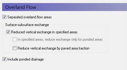
There are three main options available in the Overland Flow dialogue.
Separated overland flow areas
The first allows you to divide the model area into overland flow zones, which are conceptually areas separated by dikes or embankments. With this option, overland flow will not be allowed to flow between zones. If this is checked, then an additional item, Separated Flow Areas, will be added to the data tree.
Surface-subsurface exchange
The surface-subsurface exchange option allows you to specify an exchange coefficient to reduce the exchange of water between the overland flow and the saturated zone when the water table is at or above the ground surface.
This coefficient is also taken into account when calculating vertical infiltration from ponded water to the unsaturated zone.
If the reduced vertical exchange option is chosen then a new item, the Surface-Subsurface Leakage Coefficient, must be specified.
In specified areas, reduce exchange only for ponded areas - An additional sub-item is also available that allows you to apply the exchange coefficient in sub-areas where it is only used when water is ponded. During rainfall, this will not have an effect, as the rainfall is always added to ponded storage first. However, after the rainfall, this will allow water to flow downhill along a drainage pathway with a reduced infiltration rate.
Note
This option is only available if you are using Multi-cell Overland Flow
Reduced vertical exchange by paved area fraction - Paving is common in urban areas and has a significant impact on infiltration and runoff. This option allows you to additionally specify a paved area fraction that further reduces the infiltration in the cell by the fraction of paving.
When a Paved Area Fraction is specified, it is used as a linear scaling fraction for the Surface-Subsurface Leakage Coefficient. That is, the effective leakage coefficient is reduced by the Paved Area Fraction.
\(EffLeakCoef = (1-PAreaFrac) x SurfSubSurfLeakCoef\)
Overland Drainage
In natural systems, runoff does not travel as far as sheet flow. Rather it drains into natural and man-made drainage features in the landscape, such as creeks and ditches. Then, it generally discharges into streams, rivers or other surface water features. In urban areas, it may discharge into storm water retention basins designed to capture runoff.
The Overland Drainage (OL Drainage) allows you to specify conceptual drainage networks. Conceptually, the OL Drainage is similar to the SZ Drainage in that a drainage network is calculated based on a downhill flow path from each node until it reaches a stream, a boundary, or a local depression.
Selecting this option creates additional sub-items in the data tree for the drainage options.
b. Related Items:
- Separated Flow Areas
- Surface-Subsurface Leakage Coefficient
- Overland Flow - Technical Reference
- Working with Overland Flow and Ponding
- Overland Drainage
- Coupling of MIKE SHE and a MIKE 1D River Model
2. Manning number
a. Overview
| Manning number | |
|---|---|
| Condition | when Overland Flow + the Finite Difference method is selected in the Simulation Specification dialogue |
| dialogue Type | Stationary Real Data |
| EUM Data Units | Mannings M |
The Manning M is equivalent to the Stickler roughness coefficient, the use of which is described in Overland Flow - Technical Reference.
The Manning M is the inverse of the more conventional Mannings n. The value of n is typically in the range of 0.01 (smooth channels) to 0.10 (thickly vegetated channels). This corresponds to values of M between 100 and 10, respectively. Generally, lower values of Mannings M are used for overland flow compared to channel flow.
If you don’t want to simulate overland flow in an area, a Mannings M of 0 will disable overland flow. However, be aware that this will also prevent overland flow from entering into the cell.
Note
A time-varying value can be specified by using a time-varying dfs2 file and checking ON the time-varying option.
Related Items:
- Overland Flow - Technical Reference
- Mean-Step-Accumulated time varying parameters
- Working with Overland Flow and Ponding
3. Detention Storage
a. Overview
| Detention Storage | |
|---|---|
| Condition | when Overland Flow + the Finite Difference method is selected in the Simulation Specification dialogue |
| dialogue Type | Stationary Real Data |
| EUM Data Units | Storage Depth |
Detention Storage is used to limit the amount of water that can flow over the ground surface. The depth of ponded water must exceed the detention storage before water will flow as sheet flow to the adjacent cell. For example, if the detention storage is set equal to 2mm, then the depth of water on the surface must exceed 2mm before it will be able to flow as overland flow. This is equivalent to the trapping of surface water in small ponds or depressions within a grid cell.
The detention storage also limits the inflow into the river. Thus, overland flow into the river will only occur if the ponded depth is above the detention storage. If you are using Flood codes, then the river model will only control the water level in the cell if the water level in the river link is above the topography + detention storage.
Water trapped in detention storage continues to be available for infiltration to the unsaturated zone and to evapotranspiration. Using detention storage, you can simulate water that is trapped in depressions that are smaller than a grid cell.
Detention storage can be used effectively to improve the Overland simulation performance. In areas of permanently ponded water, you can set the Detention Storage equal to depth of ponding. This will remove these areas from the Overland Flow calculation and prevent the time step from be reduced while MIKE SHE tries to calculate lateral circulation in the ponded areas.
b. Related Items:
- Overland Flow - Technical Reference
- Overland Flow Performance
- OL Drainage Options
- Working with Overland Flow and Ponding
4. Initial Water Depth
a. Overview
| Initial Water Depth | |
|---|---|
| Condition | when Overland Flow + the Finite Difference method is selected in the Simulation Specification dialogue |
| dialogue Type | Stationary Real Data |
| EUM Data Units | Water Depth |
This is the initial condition for the overland flow calculations, which is the initial depth of water on the ground surface. The initial water depth is usually zero.
The initial water depth for overland flow is also the boundary condition for overland flow. In other words, if you specify an initial depth of 2mm, then the boundary will always have 2mm of water and there will be an inflow of water to the model whenever the internal cell has less than 2mm of ponded water.
Note
You can specify a time varying OL boundary condition using an Extra Parameter option.
b. Related Items:
- Overland Flow - Technical Reference
- Time-varying Overland Flow Boundary Conditions
- Working with Overland Flow and Ponding
5. Surface-Subsurface Leakage Coefficient
a. Overview
| Surface-Subsurface Leakage Coefficient | |
|---|---|
| Condition | when Overland Flow + the Finite Difference method is selected in the Simulation Specification dialogue AND the Reduced vertical exchange in specified areas option selected in the main Overland Flow dialogue |
| dialogue Type | Stationary Real Data |
| EUM Data Units | Leakage Coeff./Drain Time Const. |
The Surface-subsurface leakage coefficient reduces the infiltration rate at the ground surface. It works in both directions. That is, it reduces both the infiltration rate and the seepage outflow rate across the ground surface.
Conceptually, the leakage coefficient is used to account for soil compaction and fine sediment deposits on flood plains in areas that otherwise have similar soil profiles.
If the groundwater level is at the ground surface, then the exchange of water between the surface water and ground water is based on the specified leakage coefficient and the hydraulic head between surface water and ground water. In other words, the UZ model is automatically replaced by a simple Darcy flow description when the profile becomes completely saturated.
If the groundwater level is below the ground surface, then the vertical infiltration is determined by the minimum of the moisture dependent hydraulic conductivity (from the soils database) and the leakage coefficient.
This option is often useful under lakes or on flood plains, which may be permanently or temporarily flooded, and where fine sediment may have accumulated creating a low permeable layer (lining) with considerable flow resistance. It is also used to simulate soil compaction and paved areas.
The value of the leakage coefficient may be found by model calibration, but a rough estimate can be made based on the saturated hydraulic conductivities of the unsaturated zone or in the low permeable sediment layer, if such data is available.
The leakage coefficient is also applied to the vertical leakage from ponded water to the UZ model. In this case, the vertical leakage is a series calculation based on the harmonic mean of the UZ hydraulic conductivity and the leakage coefficient.
The specified leakage coefficient is used wherever it is specified. In areas where a delete value is specified, it is ignored.
In the processed data, the item, Surface-Subsurface Exchange Grid Code, is added, where areas with full contact are defined with a 0, and areas with reduced contact are defined with a 1.
Note
A time-varying value can be specified by using a time-varying dfs2 file and checking ON the time-varying option to support reduced infiltration due to frozen soil in the winter.
b. Related Items:
- Flooding from a MIKE 1D river model to MIKE SHE using Flood Codes
- Mean-Step-Accumulated time varying parameters
- Groundwater exchange with Rivers
- Overland Flow - Technical Reference
- Working with Overland Flow and Ponding
6. Sub-areas for reduced ponded exchange
a. Overview
| Sub-areas for reduced ponded exchange | |
|---|---|
| Condition | when Overland Flow + the Finite Difference method is selected in the Simulation Specification dialogue AND Surface-subsurface leakage coefficient AND In specified areas, reduce exchange only for ponded areas are both selected in the main Overland Flow dialogue |
| dialogue Type | Integer Grid Codes |
| EUM Data Units | Grid Code |
An additional sub-item is also available that allows you to apply the exchange coefficient in sub-areas where it is only used when water is ponded. During rainfall, this will not have an effect, as the rainfall is always added to ponded storage first. However, after the rainfall, this will allow water to flow downhill along a drainage pathway with a reduced infiltration rate.
b. Related Items:
- Flooding from a MIKE 1D river model to MIKE SHE using Flood Codes
- Groundwater exchange with Rivers
- Overland Flow - Technical Reference
- Working with Overland Flow and Ponding
7. Paved Area Fraction
a. Overview
| Paved Area Fraction | |
|---|---|
| Condition | when Overland Flow + the Finite Difference method is selected in the Simulation Specification dialogue and Reduced vertical exchange by paved areas is selected in the main Overland Flow dialogue |
| dialogue Type | Stationary Real Data |
| EUM Data Units | Fraction |
Paving is common in urban areas and has a significant impact on infiltration and runoff. This option allows you to additionally specify a paved area fraction that further reduces the infiltration in the cell by the fraction of paving.
When a Paved Area Fraction is specified, it is used as a linear scaling fraction for the Surface-Subsurface Leakage Coefficient. That is, the effective leakage coefficient is reduced by the Paved Area Fraction.
\(EffLeakCoef = (1-PAreaFrac) x SurfSubSurfLeakCoef\)
Note
A time-varying value can be specified by using a time-varying dfs2 file and checking ON the time-varying option.
b. Related Items:
8. Separated Flow Areas
a. Overview
| Separated Flow Areas | |
|---|---|
| Condition | when Overland Flow + the Finite Difference method is selected in the Simulation Specification dialogue and Separated Flow Areas selected in the main Overland Flow dialogue |
| dialogue Type | Integer Grid Codes |
| EUM Data Units | Grid Code |
By specifying separated overland flow areas, you can simulate areas that are separated by dikes or embankments. Separated overland flow areas are defined by specifying a .dfs2 Integer Grid Code file, containing a unique code value for each flow area. The model will then disable overland flow between grids with different flow codes. Thus, embankments can be simulated by defining different flow codes on each side of the embankment. Legal code values are 1 and higher. Delete values are not allowed inside the model area.
b. Related Items:
9. Overland Drainage
a. Overview
The OL Drainage function requires a reference system for linking the drainage to a recipient node or cell. The recipient can be a river node, another OL grid cell, or a model boundary.
The Overland Drainage module is complex. The section Overland Drainage includes a lot of helpful information on using this module
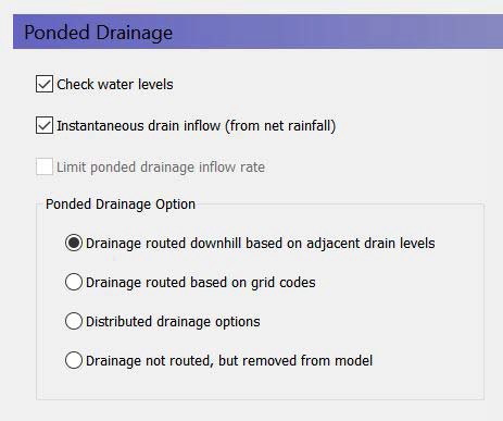
Check water levels - This means that the destination water level must be lower than the ponded water level in the cell.
Instantaneous drain inflow (from net rainfall) - If this option is ON (default), then the OL Drainage is instantaneous, and it will only be taken from net precipitation, disregarding any ponded water. If this option is OFF, then you must specify an Inflow Time Constant (new data tree item), which controls the rate of inflow to the drain. In other words, some ponding will be retained on the surface at the end of the time step - even if the time constant is very high.
Limit OL drainage inflow rate - You can optionally also specify a maximum inflow rate. If the Limited ponded drainage inflow rate option is ON, then a new data tree item for the maximum inflow rate to the drain will be added. This supports culverts, etc. that restrict drain inflow.
There are four different options for setting up the drainage source-recipient reference system
- Routed downhill based on drain levels - routed to the nearest downhill river, boundary or internal depression
- Routed based on grid codes - routed to the nearest river or boundary with the same grid code.
- Distributed drainage options - routing to specified River Links or sewer manholes
- Drainage not routed, but removed
b. Runoff Coefficient
| Runoff Coefficient | |
|---|---|
| Condition | If Overland Flow selected in the Simulation Specification dialogue and Overland Drainage selected in Overland Flow dialogue |
| dialogue Type | Stationary Real Data |
| EUM Data Units | Fraction |
The Runoff Coefficient defines the fraction of calculated drain flow that will effectively be routed to storm sewers and other surface drainage features in paved areas.
The Runoff Coefficient acts in two ways:
- it tells MIKE SHE where it should be applied, and
- the value specifies how much should be 'drained away' before the remaining water is subject to other processes like infiltration, runoff, etc.
Thus, in non-drainage cells, you should use a value of zero or an Undefined Value (-1e-35 by default). Whereas, in drainage cells, you must specify a value greater than 0 and less than or equal to 1.
If the option "instantaneous drain inflow (from net rainfall)" is not selected, the coefficient value is rather a scaling factor than a true runoff coefficient. In this case the flow into the drainage system will also be controlled by the inflow time constant, so the coefficient could be seen as the area percentage contributing to drainage.
If the "instantaneous drain inflow (from net rainfall)" option is selected, the parameter comes close to a true runoff coefficient: Any ponded water will be left on the cell, and only the specified fraction of net rainfall will be routed to the drain without any delay. Note that interception storage and when using the Richards- and gravity UZ-solvers also evapotranspiration have already been calculated at this point, so the specified fraction will be taken from the resulting net precipitation.
Note
A time-varying value can be specified by using a time-varying dfs2 file and checking ON the time-varying option.
c. Maximum Storage Change Rate
| Maximum storage change rate | |
|---|---|
| Condition | If Overland Flow selected in the Simulation Specification dialogue and Overland Drainage selected in Overland Flow dialogue |
| dialogue Type | Stationary Real Data |
| EUM Data Units | Storage change rate |
If the Specify max rate of change in storage depth option is checked, then MIKE SHE will restrict the rate at which ponded water is drained to the paved drainage function. This allows you to retain ponded water on a cell and drain it away at a specified rate to the river.
Note
A time-varying value can be specified by using a dfs2 file and checking ON the time-varying option.
d. Inflow Time Constant
| Inflow Time Constant | |
|---|---|
| Condition | If Overland Flow selected in the Simulation Specification dialogue and Overland Drainage selected in Overland Flow dialogue and Drain Inflow Retention is ON |
| dialogue Type | Stationary Real Data |
| EUM Data Units | Leakage coefficient/Drain time constant |
This is the time constant that controls the inflow rate to the Overland drainage storage.
Note
A time-varying value can be specified by using a time-varying dfs2 file and checking ON the time-varying option.
e. Outflow Time Constant
| Maximum storage change rate | |
|---|---|
| Condition | If Overland Flow selected in the Simulation Specification dialogue and Overland Drainage selected in Overland Flow dialogue |
| dialogue Type | Stationary Real Data |
| EUM Data Units | Leakage coefficient/Drain time constant |
This is the time constant that controls the outflow rate from the Overland Drainage storage to the recipient.
Note
A time-varying value can be specified as an Extra Parameter to support changing paving conditions over time.
f. Drain Level
| Maximum storage change rate | |
|---|---|
| Condition | If Overland Flow selected in the Simulation Specification dialogue and Overland Drainage selected in Overland Flow dialogue, and the Drain Level option selected |
| dialogue Type | Stationary Real Data |
| EUM Data Units | Height above ground |
This is the level that controls the source - destination reference system, the sill for flow into the drain (if the drain level is above ground) as well as the bottom of the drain storage for determining the head difference between the drain storage and the recipient (if the option "Check water levels" is ON).
Note
A time-varying value can be specified by using a dfs2 file and checking ON the time-varying option. However, this will exclude using any of the drainage distribution methods that rely on the Drain Level.
g. Drain Codes
| Maximum storage change rate | |
|---|---|
| Condition | If Overland Flow selected in the Simulation Specification dialogue and Overland Drainage selected in Overland Flow dialogue, and the Drain code option selected |
| dialogue Type | Integer Grid Codes |
| EUM Data Units | Grid Code |
The drainage reference system will be created only within a common drain code.
h. Drainage Option Distribution
| Maximum storage change rate | |
|---|---|
| Condition | If Overland Flow selected in the Simulation Specification dialogue and Overland Drainage selected in Overland Flow dialogue, and the Distributed option selected |
| dialogue Type | Integer Grid Codes |
| EUM Data Units | Grid Code |
This allows you to defined drainage to specify River Links or sewer manholes, via an Extra Parameter option.
i. Related Items
- Overland Flow - Technical Reference
- Working with Overland Flow and Ponding
- Overland Drainage
- OL Drainage to Specified River H-points
- Unsaturated Zone
10. Overland Flow Zones
a. Overview
| Overland Flow Zones | |
|---|---|
| Condition | If Overland Flow + the Subcatchment-based method is chosen in the Simulation Specification dialogue |
| dialogue Type | Integer Grid Codes with sub-dialogue data EUM |
| EUM Data Units | Grid Code |
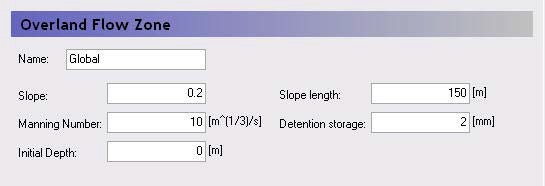
The Overland flow zones are used to define the topographic zones for the simple, catchment-based overland flow solution. The overland flow zones are typically defined as areas with similar topography. For example, the river flood plain would be a typical topographic zone, although it might be included in many subcatchments.
Each unique grid code in the Overland Flow Zones map will generate a sub-item in the data tree where the following parameters must be specified.
Slope - The Slope variable is a representative slope in the topographic area. It can be thought of as the average slope, but it is really a calibration parameter as it can’t really be calibrated to a true average.
Slope Length - Like the Slope itself, the Slope Length is a representative distance that water must travel as overland flow before reaching a ditch or stream. It can be thought of as the average travel distance, but, like the Slope, it is really a calibration parameter as it can’t really be calibrated to a true average.
Manning Number - The Manning M is equivalent to the Stickler roughness coefficient. The Manning M is the inverse of the more conventional Mannings n. The value of n is typically in the range of 0.01 (smooth channels) to 0.10 (thickly vegetated channels). This corresponds to values of M between 100 and 10, respectively. Generally, lower values of Mannings M are used for overland flow compared to channel flow.
Detention Storage - Detention Storage is used to limit the amount of water that can flow over the ground surface. For example, if the detention storage is set equal to 2mm, then the depth of water on the surface must exceed 2mm before it will be able to flow as overland flow. Water trapped in detention storage continues to be available for infiltration to the unsaturated zone and to evapotranspiration. Using detention storage, you can simulate water that is trapped in depressions that are smaller in area than a grid cell.
Initial Depth - This is the initial condition for the overland flow calculations, which is the initial depth of water on the ground surface.
b. Initial Mass (per Species)
| Initial Mass | |
|---|---|
| Condition | when water quality for Overland Flow is selected in the Water Quality Simulation Specification dialogue |
| dialogue Type | Stationary Real Data |
| EUM Data Units | Mass per unit area [e.g. g/m2] |
The initial mass for overland transport is given as a surface concentration [e.g. kg/m2]. This makes it easier to control the mass of solute introduced because you do not have to consider surface water depth.
c. Related Items:
- Solute Transport in Overland Flow
- Initial Conditions in Overland Transport
- Simplified Overland Flow Routing
- Overland Flow - Technical Reference
- Working with Overland Flow and Ponding
11. Dispersion coefficient along columns/rows
a. Overview
| Dispersion coefficient along columns/rows | |
|---|---|
| Condition | when water quality for Overland Flow is selected in the Water Quality Simulation Specification dialogue |
| dialogue Type | Stationary Real Data |
| EUM Data Units | Dispersion coefficient |
For the overland flow transport, two dispersion coefficients are required - one along the rows and the other along the columns.
Note
Unlike for the unsaturated and saturated flow, the overland transport module requires the actual dispersion coefficient [m2/s] - not the dispersivity [m].