Working with Sewers - User Guide
Five types of exchange are available when linking a MIKE+ collection system model to MIKE SHE. Three types of exchange are specified in MIKE+ only, while the other two require specification in both MIKE+ and MIKE SHE.
The exchange types are summarized in the table below.
Table 28.1 Specification of exchanges between a MIKE+ collection system model and MIKE SHE
| Exchange type | Summary | MIKE+ specification | MIKE SHE specification |
|---|---|---|---|
| MIKE SHE overland flow exchange with MIKE+ manholes | Coupling of overland flow in MIKE SHE to sewer manholes. Not overland drain flow (see below). | Exchange parameters are assigned to manholes under Groundwater couplings. | None. MIKE SHE reads the MIKE+ setup at runtime and identifies the locations of coupled manholes. Exchange takes place at the MIKE SHE grid cell in which the manhole is located. |
| MIKE SHE overland drainage to MIKE+ manholes | Coupling of overland drainage in MIKE SHE to sewer manholes. | One or more drain codes are assigned to each manhole under Groundwater couplings. Instead of (or in addition to) a specific drain code "-1" can be used to allow automatic linkage | Cells that drain to each manhole are given that manhole's code in the Drain Codes file. The cells must also be given the value 4 in the drainage Option Distribution file. In other words, the Drainage Option Distribution specification informs MIKE SHE that the cell drains to a manhole, and the Drain Codes specification identifies which manhole. The special drain code "-1" lets the cell drain to the closest manhole with active drainage, drain code "-1" and a level at or below the cell ground level. |
Table 28.1 Specification of exchanges between a MIKE+ collection system model and MIKE SHE
| Exchange type | Summary | MIKE+ specification | MIKE SHE specification |
|---|---|---|---|
| MIKE SHE saturated drainage to MIKE+ manholes | Coupling of saturated zone drainage to manholes. | Same as for overland drainage to manholes | Same as for overland drainage to manholes. |
| Exchange between MIKE SHE overland flow and MIKE+ pipes | Coupling of MIKE SHE overland flow and MIKE+ pipe flow. Only relevant for open pipes. | Exchange parameters are assigned to pipes under Groundwater couplings. | None. MIKE SHE reads the MIKE+ setup at runtime and identifies the locations of coupled pipes. Exchange takes place at the MIKE SHE grid cell in which the pipe is located. |
More details about linking MIKE SHE drain flows to a collection system model are provided below.
1. MIKE SHE SZ drain flow to Sewer model manholes
If drain flow is specified in MIKE SHE, then the drainage can be discharged to a sewer manhole. The flow in the drain is calculated by MIKE SHE based on the groundwater height above the drain level.
In MIKE SHE the distributed drainage option must be chosen (see Drainage and the cells that drain to a manhole must have an option value of 4 (see Option Distribution). The references between the MIKE SHE drain codes and the sewer manholes are defined in MIKE+. A manhole that has the drain code -1 (either as the only drain code or among other drain codes) will be used as a drain target if it is the closest one to a cell that has a drain code -1 and is at or above the level of that manhole.
2. MIKE SHE Overland Drainage to Sewer model manholes
If the Overland Drainage option is used in MIKE SHE, then the draining water can be discharged to a sewer manhole. Drain flow is calculated by MIKE SHE based on parameters defined in the ponded drainage specification.
In MIKE SHE the distributed drainage option must be chosen (see Overland Drainage) and the cells that drain to a manhole must have an option value of 4 (see Distributed drainage options). The references between the MIKE SHE drain codes and the sewer manholes are defined in MIKE+. A manhole that has the drain code -1 (either as the only drain code or among other drain codes) will be used as a drain target if it is the closest one to a cell that has a drain code -1 and is at or above the level of that manhole.
3. Sewer Outlets to MIKE SHE
Sewer outlets cannot directly discharge to MIKE SHE’s overland flow. To work around this, you can add a dummy manhole to your sewer model pipe and then couple the pipe to the outlet via a small diameter dummy pipe (See Figure 28.1). This will force most of the water out of the manhole and into MIKE SHE’s overland flow. Downside of this method, is that the head loss at the outlet is over estimated, because the discharge velocity is zero at a manhole.
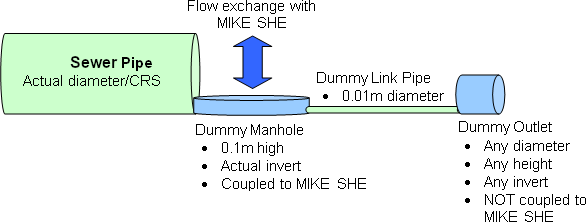
Figure 28.1: Work around for discharging sewer model outlets to MIKE SHE
Miscellaneous parameters
Smoothing of SZ exchange: Ensures a smoother calculation of flows to the sewers when the MIKE SHE time steps are large compared to the MIKE 1D sewer model time step. The sewer coupling is only made at every integer multiple of the MIKE SHE time step. If the Smooth option is not activated, the flows to the sewer can stop after a number of MIKE 1D time steps because the calculated flow volume exceeds the volume of the MIKE SHE SZ/overland grid cells. The Smooth option tries to use a reduced flow rate which equals the available volume/coupling time.
Limit inflow: This can be activated so the sewer volume + inflow does not exceed a specified fraction of the maximum sewer volume. This is used to avoid instabilities due to high pressure.
Limit outflow: This can be activated so the sewer volume - outflow doesn't come below a specified fraction of the maximum sewer volume. This is used to avoid instabilities due to drying/negative volume.
Output Files
Output from the coupled run is written to a number of .dfs0 results files- all located in the standard results directory. In the case of storing reaches, there is one item in the .dfs0 file for each storing reach.
Table 28.2 File names and conditions for output for the MIKE SHE-sewer coupling. ’setupname’ refers to the name of the model setup file
| File Name | Item Name | The file is created when... |
|---|---|---|
| .\setupname\setupname_ SZ2MouseReaches.dfs0 | "Reach [n]" (storing reaches cannot be named) | ...the MIKE SHE SZ coupling is included and storing reaches have been specified. |
| .\setupname\setupname_ OL2MouseReaches.dfs0 | "Reach [n]" (storing reaches cannot be named) | …the MIKE SHE Overland coupling is included and storing reaches have been specified. |
| .\setupname\setupname_ OL2MouseManholes.dfs0 | "\<name of manhole>" | ...the MIKE SHE Overland flow coupling to manholes is included. |
| .\setupname\setupname_ SZDrain2MouseManholes.dfs0 | "\<name of manhole> \<drain code>" | ...the MIKE SHE SZ drain coupling to manholes is included |
| .\setupname\setupname_ OLDrain2MouseManholes.dfs0 | "\<name of manhole> \<drain code>" | ...the MIKE SHE OL drain coupling to manholes is included |
Warning Messages
Exchange inflows reduced
Warning: Exchange inflows from Overland to MOUSE reduced by Overland house-keeping in order to avoid instabilities
No. of time steps: 27000 of 27000 Total a priori inflows: 1332286 m3
Total reduced inflows: 920643.0 m3 (69.10%)
MIKE SHE calculates tine in/out flows after an overland time step and feeds them to the sewer model for one or more MIKE 1D time steps. The calculations of these flows are not included in the implicit overland flow solver. Thus, the “Total a priori flows” are the rough inflows calculated using Equation 27.16). However, to prevent water balance errors, MIKE SHE checks the volume of water available in the grid cell. If the volume is insufficient, then the inflow is reduced to the available amount. The final value of inflows is the “Total reduced inflows”. Note though that the total NET inflow to the sewers will be less than this value if the flow goes from the sewers to MIKE SHE in other grid cells or other time steps.
Ideally, the Total reduced inflow should be 100%, but in practice this is rarely achieved.
Water Balance Limitations
The interaction with MIKE SHE is not included in the MIKE 1D Summary HTML file. Thus, the water added from MIKE SHE appears as an error (i.e. 6: Continuity balance in MIKE 1D).