Parameters
1. Extra Parameters
The Extra Parameters Section is available to support new features in MIKE SHE that are not yet supported in the dialogues and data tree. Detailed descriptions of the features that use Extra Parameters are found in Extra Parameters.
If you need to activate a feature that is only supported in the Extra Parameters section, you must first add the necessary number of lines to the Extra Parameters table. Then fill in the data that is required for the module.
| Type | Description |
|---|---|
| Name | this is the name of the parameter that is required by the unsupported feature. It must be spelled exactly as specified in the documentation. In may be the actual name of the feature or the name of a parameter. |
| Type | The type is the type of parameter. The following types are available: |
| Float | Real, floating point number |
| Integer | Integer number |
| Boolean | an On/Off checkbox - typically used to turn a feature on or off |
| Text | a character string |
| file name | this is typically the file where more detailed input data is recordedr |
2. Climate
a. Temperature coupling between Rivers and MIKE SHE
Temperature is not a feature that can currently be modelled in MIKE SHE though MIKE 1D has the possibility of modelling a heat balance in the stream. The heat balance in the stream is depended on the temperature of the lateral sources in the river. This option does not introduce temperature modelling in general in MIKE SHE, but rather it gives the user the possibility to introduce a temperature forcing on the water which is passed from MIKE SHE to the river either as base flow, overland or drain flow. The temperature is in turn received by MIKE 1D as though it came from MIKE SHE which makes it versatile for a later potential full implementation of temperature modelling in MIKE SHE. The functionality allows you to
- Define temperature as a spatially distributed, time varying property in MIKE SHE for ponded water and groundwater.
- Pass temperature as a property of the baseflow, overland flow and drain flow.
- Add a temperature property to the baseflow and drain flow based on the temperature of the SZ cell where the flow originates from.
- Add a defined temperature property to the ponded water.
- Use a volume based mixing function for OL and SZ drainage.
- Make cell temperature an OpenMI exchange item, so that you can access cell temperature during the simulation.
The above functionality will allow users to specify the temperature of the groundwater and ponded water. However, it will not provide the functionality to transport temperature as a property in MIKE SHE. In other words, the temperature is a defined property and there is no internal mixing or recalculation of cell temperature as a function of cell-by-cell flow. The temperature distributions are supplied through the use of extra parameters in the Extra Parameters table.
Option setup
To initiate the temperature module, you need to specify the following:
| Parameter Name | Type | Value |
|---|---|---|
| user specified temperature | Boolean | On |
| If the above is true, then you must also specify: | ||
| distributed ol temperature | Boolean | On/Off |
| distributed drain temperature | Boolean | On/Off |
| distributed sz temperature | Boolean | On/Off |
Temperature of ponded water
The temperature of the ponded water is generally controlled by the air temperature, but it is not linked to the air temperature specified in the user interface. The temperature of the ponded water also controls the temperature of the water in the OL-drains.
| Parameter Name | Type | Value |
|---|---|---|
| If distributed OL temperature is OFF (then dfs0 input): | ||
| ol temperature dfs0 file name | file name | .dfs0 file |
| ol temperature item number | integer | item number in dfs0 file, greater than zero |
| If distributed OL temperature is ON (then dfs2 input): | ||
| ol temperature dfs2 file name | file name | .dfs2 file |
| ol temperature item number | integer | item number in dfs2 file, greater than zero |
Temperature of OL drainage water
The OL drainage water is the same temperature as the source ponded water. There is no change in temperature while the water is in the drain. This is consistent with the fact that the OL drain water is controlled by the same air temperature as the ponded water in general.
Temperature of SZ drainage water
The SZ drainage water is treated separately from the SZ water because it does not travel directly to the river, but via surface water channels.
| Parameter Name | Type | Value |
|---|---|---|
| If distributed drainage temperature is OFF (then dfs0 input): | ||
| drain temperature dfs0 file name | file name | .dfs0 file |
| drain temperature item number | integer | item number in dfs0 file, greater than zero |
| If distributed drainage temperature is ON (then dfs2 input): | ||
| drain temperature dfs2 file name | file name | .dfs2 file |
| drain temperature item number | integer | item number in dfs2 file, greater than zero |
Temperature of SZ water
The SZ water is sent to the River directly via the baseflow component.
The SZ temperatures have to be specified for every layer as either all dfs0 files or all dfs2 files, depending on the initialization above.
| Parameter Name | Type | Value |
|---|---|---|
| If distributed SZ temperature is OFF (then dfs0 input): | ||
| sz temperature layer 1 dfs0 file name | file name | .dfs0 file |
| sz temperature layer 1 item number | integer | item number in dfs0 file, greater than zero |
| sz temperature layer n dfs0 file name | file name | .dfs0 file |
| sz temperature layer n item number | integer | item number in dfs0 file, greater than zero |
| If distributed SZ temperature is ON (then dfs2 input): | ||
| sz temperature layer 1 dfs2 file name | file name | .dfs2 file |
| sz temperature layer 1 item number | integer | item number in dfs2 file, greater than zero |
| sz temperature layer n dfs2 file name | file name | .dfs2 file |
| sz temperature layer n item number | integer | item number in dfs2 file, greater than zero |
b. Negative Precipitation
Negative precipitation is sometimes required when net groundwater recharge has been calculated using an external program, such as DAISY GIS. In this case, the evapotranspiration may exceed infiltration leading to a net upward flux of water from the groundwater table. However, the standard precipitation module in MIKE SHE does not recognize negative rainfall. In this case, you must specify the negative rainfall using the following Extra Parameters options:
| Parameter Name | Type | Value |
|---|---|---|
| use negative precipitation | Boolean | On |
| If the negative precipitation is uniformly distributed: | ||
| negative precipitation max depth | float | greater than zero |
| negative precipitation max layer | integer | greater than zero |
| If the negative precipitation is spatially distributed: | ||
| negative precipitation max depth dfs2 file | file name | .dfs2 file |
| negative precipitation max depth dfs2 item | integer | item number in dfs2 file, greater than zero |
| negative precipitation max layer dfs2 file | file name | dfs2 file |
| negative precipitation max layer dfs2 item | integer | item number in dfs2 file, greater than zero |
Max depth
This represents the depth of the root zone plus the thickness of the capillary fringe and is the maximum depth from which negative precipitation can be extracted.
Max layer
This is the maximum layer depth from which negative precipitation can be extracted.
Note
The negative precipitation option will only work if there is no UZ model active.
c. Precipitation multiplier
To facilitate calibration and sensitivity analysis of recharge, in models where measured precipitation is not being used, a multiplication factor has been implemented.
| Parameter Name | Type | Value |
|---|---|---|
| precipitation factor | float | greater than zero |
If this extra parameter is used, then all precipitation values are multiplied by the factor prior to being used in MIKE SHE.
3. Rivers
a. Order of creating river links
By default, MIKE SHE always processes the branches in the same order, regardless of sorting in MIKE+. To do the processing in the same order the branches are stored in MIKE+, set this extra parameter to true. This can be useful when a model is required to give the same results it gave with an older version of MIKE SHE, where the branches would always be processed in the order given by the river model setup:
| Parameter Name | Type | Value |
|---|---|---|
| disable initial branch sorting | Boolean | on |
b. Irrigation River Source Factors
A global “river source volume factor” and “river source discharge factor” are available as extra parameters for increased control of river sources during irrigation.
| Parameter Name | Type | Value |
|---|---|---|
| river source volume factor | float | positive |
| river source discharge factor | float | 0 or positive |
None, one, or both can be specified. If the factor is not specified, then a Volume factor of 0.99 and a Discharge factor of 0.0 will be used.
The factors are used in the calculation of the available water (depth) of a river source:
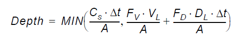
Equation 42.01
where:
- \(Depth\) is the available water depth in the river link
- \(C_s\) is the source capacity
- \(\Delta_t\) is the time step length
- \(F_v\) is the specified volume factor
- \(V_L\) is the volume of water in the link
- \(F_D\) is the specified volume discharge
- \(D_L\) is the river link discharge
- \(A\) is the cell area
The river link discharge is the same as used when checking with the threshold discharge for switching on/off the source. It is the absolute discharge in the middle of the MIKE SHE river link, interpolated between two river H-points.
MIKE SHE prints the following message in the xxx_WM_Print.log file when the parameters are specified:
Extra-parameter specified:
river source volume factor
value = 1.500000

Extra-parameter specified:
river source discharge factor
value = 1.000000
MIKE SHE also prints the following warnings in the xxx_WM_Init_Messages.log file if one or both of the factors may result in water balance errors or numerical instabilities.
WARNING: Specified value for river source volume factor is greater than 1 : 1.500000.

There is a risk of water balance errors and/or instabilities in the coupling between MIKE SHE and MIKE 11.


WARNING: Specified value for river source discharge factor is greater than 0 : 1.000000.

There is a risk of water balance errors and/or instabilities in the coupling between MIKE SHE and MIKE 11.
Note
This option is less useful now that River Sources are defined by both an Upstream and Downstream chainage. The option is maintained for backward compatibility.
c.Validation of HD Res file
In some cases, you may want to turn off the time stamp validation for the MIKE 1D output files. For example, this may be useful if you are linking older existing river models as input for the MIKE SHE WQ.
| Parameter Name | Type | Value |
|---|---|---|
| disable validation of HD res file | Boolean | On |
4. Overland Flow
a. Time-varying Overland Flow Boundary Conditions
The default boundary condition for Overland Flow in MIKE SHE is a constant water level on the outer boundary. The value of this boundary condition is determined by the initial water depth on the boundary. In most models the recommended value is a water depth of zero. In this case, if the water level adjacent to the boundary increases, water will discharge across the boundary and out of the model. If you want to prevent overland outflow, then you can use the Separated Flow Areas option to restrict lateral flow out of the model.
If you specify a non-zero value for initial water depth on the boundary, then this value becomes a constant for the entire simulation. If the water level inside the model decreases below this value, the boundary will act as an infinite source of inflow to the model.
However, in many models - especially those with significant wetland areas - the constant water level condition on the boundary is too restrictive.
The following extra parameter options allow you to specify a time varying condition for the outer boundary of the overland flow. If you initialize this option, then you must supply a dfs2 integer grid code file that defines the locations at which you want a time varying boundary. The input requirements have been set up such that you can re-use the model domain dfs2 output file from the pre-processor. In the model domain pre-processed output, the outer cells are defined by a value of 2 and the inner cells are defined by a value of 1.
If the grid code value on the boundary is:
- 2 - the cell is a time varying boundary node, or
- 1 - the cell will have a constant water depth equal to the initial water depth.
The second required file is the actual time-varying water level values. These can be obtained from any MIKE SHE simulation, where the overland water elevation has been stored as a grid series output. There is no requirement that they be stored on the same grid. Internally, the actual boundary condition values will be interpolated from the nearest input values. Thus, the OL boundary conditions can be taken from a coarse regional model and applied to a local scale model.
Finally, each file name must be accompanied by an integer item number that defines which item in the dfs2 file should be used.
| Parameter Name | Type | Value |
|---|---|---|
| time varying ol boundary | Boolean | On |
| ol boundary code file name | filename | .dfs2 file |
| ol boundary code item number | integer | item number in dfs2 file, greater than zero |
| ol boundary head file name | filename | .dfs2 file |
| ol boundary head item number | integer | item number in dfs2 file, greater than zero |
The Hot Start function is not impacted by the time varying OL boundary. If the continuing simulation includes the time varying OL function, then it will be used. If the continuing simulation does not include the time varying OL function the head from the hot start time point.
b. Simplified Overland Flow options
Avoiding the redistribution of ponded water
In the standard version of the Simplified Overland Flow solver, the solver calculates a mean water depth for the entire flow zone using the available overland water from all of the cells in the flow zone. During the Overland flow time step, ET and infiltration are calculated for each cell and lateral flows to and from the zone are calculated. At the end of the time step, a new average water depth is calculated, which is assigned to all cells in the flow zone.
In practice, this results in a redistribution of water from cells with ponded water (e.g. due to high rainfall or low infiltration) to the rest of the flow zone where cells potentially have a higher infiltration capacity. To avoid this redistribution, an option has been added where the solver only calculates overland flow for the cells that can potentially produce runoff, that is, only in the cells for which the water depth exceeds the detention storage depth.
| Parameter Name | Type | Value |
|---|---|---|
| only simple OL from ponded | Boolean | On |
Routing simple overland flow directly to the river
In the standard version of the Simplified Overland Flow solver, the water is routed from 'higher' zones to 'lower' zones within a subcatchment. Thus, overland flow generated in the upper zone is routed to the next lowest flow zone based on the integer code values of the two zones. In other words, at the beginning of the time step the overland flow leaving the upper zone (calculated in the previous time step) is distributed evenly across all of the cells in the receiving zone. In practice, this results in a distribution of water from cells in the upstream zone with ponded water (e.g. due to high rainfall or low infiltration) to all of the cells in the downstream zone with potentially a large number of those cells having a higher infiltration capacity. In this case, then, overland flow generated in the upper flow zone may never reach the stream network because it is distributed thinly across the entire downstream zone.
To avoid excess infiltration or evaporation in the downstream zone, an option was added that allows you to route overland flow directly to the stream net- work. In this case, overland flow generated in any of the overland flow zones is not distributed across the downstream zone, but rather it is added directly to the river stream network as lateral inflow.
| Parameter Name | Type | Value |
|---|---|---|
| no simple OL routing | Boolean | On |
c. Explicit Overland Flow Output
If you are using the explicit overland flow solver, the time step depends on the location in the model with the critical Courant criteria. The grid series output allows you to save the Courant criteria, so that you can see where the critical locations are. However, the grid series output is an average Courant number over the storing time step, where there can be hundreds of OL time steps in a storing time step. If you are experiencing very short time steps due to short duration rainfall events, for example, the critical information can be difficult to distill from the dfs2 grid series output.
To make it easier to find the critical locations, an extra parameter option was added that writes out the critical locations at every time step, if the time step is reduced below a user-defined fraction of the storing time step.
| Parameter Name | Type | Value |
|---|---|---|
| adaptive OL time step info threshold fraction | Float | between 0.0 and 1.0 Default = 0.0001 |
The default value is 0.01. This means that if the reduced time step is less than 0.1 times the Max OL time step, then a message will be printed in the _WM.log file. Such as:
Adaptive time step info from Explictit OL solver:
OL step no: 59: ... Final time step = 1.8108 seconds

with the following four reasons:

Critical: OL Wave Courant number. Cell (8,21)...

Critical: Net outflow from OL cell to River. Cell (8,21) ...

Critical: Net OL outflow from cell. Cell: (17,19) ...

Critical: Net outflow from River to OL. River link between ...
If you experience frequent severe reductions in the OL time step when using the explicit OL solver, then this threshold can cause very large log files to be created. If you are not interested in this information, then you can reduce this threshold to reduce the frequency of the output.
d. Alternative low gradient damping function
In flat areas with ponded water, the head gradient between grid cells will be zero or nearly zero, which means that as the gradient goes to zero \(\delta_t\) also goes to zero. To allow the simulation to run with longer time steps and dampen any numerical instabilities in areas with low lateral gradients, the calculated intercell flows are multiplied by a damping factor when the gradients are close to zero.
Compared to the default damping function, an alternative damping function is available as an Extra Parameter that goes to zero more quickly and is consistent with the function used in the MIKE+ 2D Overland module.
To activate the alternate function, you must specify the following Boolean parameter in the Extra Parameters dialogue:.
| Parameter Name | Type | Value |
|---|---|---|
| Enable Alternative Damping Function | Boolean | On |
The alternative function is a single parabolic function. For more detail, see the section Low gradient damping functionin the Reference manual.
e. OL Drainage Options
By default, the OL Drainage function routes the available ponded water to the OL drainage network. However, the available ponded depth does not include the detention storage. If you want to route all of the ponded water in a cell - including the water in detention storage - to the OL Drainage network, then you can define the following Extra Parameter:
| Parameter Name | Type | Value |
|---|---|---|
| allow paved routing of detention storage | Boolean | On |
By default, the OL Drainage will occur no matter the elevation of the destination cell. In some cases, this could lead to unrealistic drainages. For example, OL drainage on a flood plain mapped to a river will always drain to the river, even if the river is higher than the drain level. To counter such unrealistic conditions, this Extra Parameter will prevent OL drainage in the case where the drain level is below the bed level of the river.
Note
This check is between the Drain level and the Bed level - not between the dynamic water levels.
| Parameter Name | Type | Value |
|---|---|---|
| check OL-drain level against bed level' | Boolean | On |
The interaction between the multi-cell OL solution and the OL drainage is complex and could lead to some unexpected results. Further, the multi-cell OL solution is more likely to be used as a more physical representation of the drainage rendering the OL drainage obsolete in this case. This option allows you to disable OL drainage when using the multi-cell OL approach.
| Parameter Name | Type | Value |
|---|---|---|
| disable multi-cell OL-drainage | Boolean | On |
f. OL Drainage to Specified River H-points
The Distributed Drainage option allows you to route drainage from the OL drainage directly to river H-points. This is different from the normal drainage function, which routes OL drainage to river links rather than directly to H-points. Further, this option can route drainage to river branches that are not defined in the MIKE SHE coupling dialog of MIKE+.
The following steps are required to activate this option:
- Create a pfs file containing information for each specified drainage area to be routed to the specific river H-points..
| Line item | Comment |
|---|---|
| [MIKESHE_MIKE11DrainageReach_File] | |
| [SpecifiedMIKE11ReachesForDrainage] NrOfReaches = 1 RiverChainageUnit = 'meter' |
NrOfReaches is the number of items specified in the section below |
| [Reach_1] DrainCode = 1 BranchName = 'Lammehavebækken' Upstream_Chainage = 6000. Downstream_Chainage = 8459 EndSect // Reach_1 |
For each specified reach, you must include a section specifying the MIKE SHE drain code, and the river branch name and the upstream and downstream chainage. |
| EndSect // SpecifiedMIKE11ReachesForDrainage | |
| EndSect // MIKESHE_MIKE11DrainageReach_File |
Note
The pfs files line text refers to M11, but refers to either MIKE 11 or MIKE 1D.
The drain code references the area that OL drainage is routed to the specified river branch and chainage. The drain code must be greater than or equal to zero. Drain code values equal to zero (0) are not included in the reference drainage system. Furthermore, an error condition will occur if the specified drain code does not exist in the drainage code file used in MIKE SHE.
The branch name must be spelled correctly and include all spaces contained in the name, if any. The branch name should be enclosed in quotes. An error condition will occur if the specified branch is not present in the river network.
The chainages refer to the starting and ending chainage of the specified branch which drainage is routed to. The interval does not have to correspond exactly to specific river H-points because the MIKE SHE pre-processor finds the closest H-points to the specified interval. If the upstream and downstream chainages are the same, the drainage discharge is routed to the closest H-point.
- Add the following items to the Extra Parameters list
| Parameter Name | Type | Value |
|---|---|---|
| use specified reaches for OL- drainage | Boolean | On |
| specified reaches for OL-drainage | file name | the pfs file name, including the path |
- In the OL Drainage item under the Overland flow, select distributed drainage options. See Overland Drainage.
- Specify drain codes is the same manner as usual. Remember that all drain codes in the pfs file must exist in the active domain of the model or you will get an error.
- Specify where the Distributed drainage option should be used in Drainage Option Distribution item in the data tree under the Overland Flow. Distributed drainage will be used in all cells with a value of 3. If a combination of the original drainage method and the Distributed drainage option is going to be used, 2 should be used for areas using the original drainage option and 3 should be used where you want the Distributed drainage option to be used.
- Pre-process and run your MIKE SHE model normally.
If the MIKE SHE setup does not successfully pre-process you should review the above steps to see if you have any error in the setup. The _PP_Print.log file in your simulation subdirectory should help you identify why the MIKE SHE setup failed to pre-process.
If the MIKE SHE setup successfully pre-processes you should also look at the pre-processed data (on the Processed data tab) and the _PP_Print.log file in your simulation subdirectory to make sure you are comfortable with how the preprocessor has set up the drainage reference system. You can search for “Making setup of Specified \<MIKE 11\MIKE 1D> Reaches For \<SZ\OL> Drainage” in the _PP_Print.log file to find the start of the section that details the drainage reference system.
Water balance
The water balance utility can be used to look at differences between drainage discharges from areas using the original drainage option and the Distributed Drainage option. The MIKE SHE water balance configuration file (MSHE_Wbl_Config.pfs in the installation directory) should be reviewed to see which water balance types segregate standard drainage flow (data type ol.qoldrtorivin) and Distributed drainage flow (data type ol.qoldrtoM11Hpoint) (see Using the Water Balance Too)
5. Unsaturated Zone
a. UZ-SZ exchange
In some cases, a local water balance error is generated during the UZ-SZ exchange. This can occur when the water table is rising faster than the solution scheme can keep up. There is an Extra Parameter that can help if you notice such condition:
| Parameter Name | Type | Value |
|---|---|---|
| max iterations UZ-coupling | Integer | greater than or equal to 10 |
The internal default value in MIKE SHE is 10, but you may find a value of between 200 and 500 yields better results if you are seeing some local water balance issues. The impact on run-time is marginal, as the extra iterations are not used if the solution converges earlier.
b. Transpiration during ponding
In general, plants are not very tolerant of saturated soil in their root zone. Saturated soil is quickly depleted of oxygen and the roots will soon die. MIKE SHE normally takes care of this automatically by removing ET from ponded water before calculating transpiration from the unsaturated or saturated zones. If there is sufficient ponded water, then the entire ET will be satisfied from the ponded water.
However, some plants, such as rice, are more tolerant of saturated soils and still extract ET from saturated soils, although normally at a reduced rate. If ET from the soil zone is ignored, then the distribution of water supplied to ET will be incorrect.
The transpiration during ponding option changes the order in which the ET is calculated. In this case, the ET rate is multiplied by an anaerobic tolerance factor and ET is removed from the soil before being removed from the ponded water.
| Parameter Name | Type | Value |
|---|---|---|
| allow transpiration during ponding | Boolean | On |
| global anaerobic tolerance factor | Float | Greater than or equal to 0 Less than or equal to 1 |
| optional (instead of global value) | ||
| anaerobic tolerance factor dfs2 file name | file name | .dfs2 file |
| anaerobic tolerance factor item number | integer | item number in dfs2 file, greater than zero |
c.Threshold depth for infiltration (2-Layer UZ)
The 2-Layer water balance method for the unsaturated zone does not include evapotranspiration from the soil surface. Thus, even a small amount of water on the ground surface will infiltrate. If you use this extra parameter, then you can define a depth of overland water that must be exceeded before infiltration will occur. This keeps small amounts of precipitation from infiltrating and allows them to evaporate instead.
The calculated infiltration is simply reduced if the remaining overland water depth will be smaller than the specified threshold value.
| Parameter Name | Type | Value |
|---|---|---|
| use threshold depth for infiltration | Boolean | On |
| threshold depth for infiltration meter | Float | Greater than zero |
Note
This option is less useful with the ET Deficit Factor introduced in the 2008 Release, which maintains ET at the full rate until the specified deficit is reached.
6. Saturated Zone
a. Sheet Pile Module
The Sheet Piling module is not yet included in the MIKE SHE GUI. However, the input for the module is fairly simple and is handled via the Extra Parameters options
The Sheet Piling module is activated by including the following two parameters in the Extra Parameters section of the data tree, and creating the required module input file:
| Parameter Name | Type | Value |
|---|---|---|
| sheet piling module | Boolean | On |
| sheet piling file | file name | the file name of the Sheet Pile input file |
Sheet Pile Location
The location of the sheet piles is defined using a dfs2 file with integer grid codes. One file (or item) is required for each computational layer with sheet piling. Each file must have the same grid size as the MIKE SHE model. The grid codes are “composed” of simple sums of 100, 10, 1, 0 where:
100 = a N-S sheet piling “link” between the actual cell and the next cell in positive x-direction,
10 = a E-W sheet piling “link” between the actual cell and the next cell in the positive y-direction,
1 = a Horizontal sheet-piling “surface” between the actual layer and the layer above (ground surface if actual layer is 1), and
0 = no sheet piling.
Thus, for example, a cell containing the code “110” defines the existence of sheet piling along the Eastern and Northern cell boundaries. A cell containing the code “11” defines a sheet piling along the Northern cell boundary and at the top of the layer.
Leakage Coefficient
The Leakage Coefficient is required for flow in the x-, y-, and z-direction for each layer containing sheet piling. The Leakage Coefficient is required in the x-direction if any cell contains a “100” value, in the y-direction if any cell contains a “10” value, and in the z-direction if any cell contains a “1” value.
The leakage coefficients can be specified as a global value (per layer) or as a distribution in a dfs2 file. In the case of a dfs2 file, the values must be specified in the cells where the grid codes are specified. The EUM type (unit) of the dfs2 files must be “Leakage coefficient/Drain time constant” with the unit 1/Time.
Top and bottom levels (optional)
This option can be used when the vertical sheet piling only extends across part of a layer. The levels are specified in the same cells as the leakage coefficients in the x- and y-direction, one set of top and bottom levels for each direction.
The levels can be specified as global values (per layer) or as a distribution in a dfs2 file. Both can be absolute levels or relative to ground. The EUM type of the dfs2 files must be “elevation” for absolute levels, and “depth below ground” (positive values) or “height above ground” (negative values) when specified relative to the ground surface. The type and unit of the global value is “elevation” (m) when absolute, and “height above ground” (m) (negative value) when relative.
In cells where the sheet pile extends across the entire layer, the top and bottom levels should simply be set to large positive and negative values respectively (e.g. 1.0E+30 and -1.0E+30).
Input File for the Sheet Pile Module
The name of the input file is specified in the Extra Parameters section described above. The file has the general MIKEZero parameter file (pfs) format. The exact format of the file is given below, along with a description of the different data items.
Note
The pfs format must be adhered to exactly. There is a small utility (pfsEditor.exe) in the installation \bin directly that you can use for editing and testing pfs files that you create.
| Line item | Comment |
|---|---|
| [MIKESHE_SheetPiling_File] FileVersion = 2 [SheetPiling] |
FileVersion can be 1 or 2, but must be 2, if you want to check for the SpecifiedXYLevels option |
| NrOfLayers = 1 | Total number of SZ layers with sheet piling |
| SpecifiedXYLevels = 1 | 0: not specified. 1: top and bottom levels specified for each layer Note: only checked when FileVersion > 1 |
| [Layer_1] | This section must be repeated for each -NrOfLayers- sheet piling layer. The sections must be named Layer_1, Layer_2, etc. |
| LayerNumber = 1 | The MIKE SHE SZ layer number of the actual sheet piling layer (1 = top layer). |
| [GridCodes] Type = 1 FixedValue = 0 [DFS_2D_DATA_FILE] FILE_NAME = |.\SPGrid_1.dfs2| ITEM_COUNT = 1 ITEM_NUMBERS = 1 EndSect // DFS_2D_DATA_FILE EndSect // GridCodes |
[GridCodes] section Specification of grid codes for the current layer. Type Normally 1 because a dfs2 file is required. 0 means global value. FILE_NAME Name of the dfs2 file with grid codes. The file name is enclosed in "|" which tells the system that the name is relative to the location of this module input file. ITEM_NUMBERS: One number (because ITEM_COUNT must be 1) defining the item of the dfs2 file to be used. |
| [X_Leakage] Type = 0 FixedValue = 1.0E-7 [DFS_2D_DATA_FILE] FILE_NAME = |.\maps\SPLeakX_1.dfs2| ITEM_COUNT = 1 ITEM_NUMBERS = 1 EndSect // DFS_2D_DATA_FILE EndSect // X_Leakage |
[X_Leakage] section: Required if there are any cells with N-S sheet piling affecting the flow in the x-direction (codes containing 100). Type Set to 0 if a global value is specified and 1 if using a dfs2 file. FixedValue The global value (1/s) which is read if Type = 0. FILE_NAME and ITEM_NUM- BERS Dfs2 file name and item number if Type = 1 (relative file name as explained under Grid Codes). |
| [Y_Leakage] Type = 0 //(0:Fixed value,1:DFS2 file) FixedValue = 2.0E-7 [DFS_2D_DATA_FILE] FILE_NAME = |.\maps\SPLeakY_1.dfs2| ITEM_COUNT = 1 //(must be 1) ITEM_NUMBERS = 1 1 EndSect // DFS_2D_DATA_FILE EndSect // Y_Leakage |
Y_Leakage] section: Required if there are any cells with E-W sheet piling affecting the flow in the y-direction (codes containing 10). |
| [Z_Leakage] Type = 0 //(0:Fixed value,1:DFS2 file) FixedValue = 3.0E-7 [DFS_2D_DATA_FILE] FILE_NAME = |.\maps\SPLeakZ_1.dfs2| ITEM_COUNT = 1 ITEM_NUMBERS = 1 EndSect // DFS_2D_DATA_FILE EndSect // Z_Leakage |
[Z_Leakage] section: Required if there are any cells with horizontal sheet piling affecting the vertical flow (codes containing 1). |
| [X_TopLevel] RelativeToGround = 0 // 0: no, 1: yes Type = 1 //(0:Fixed value,1:DFS2 file) FixedValue = 0.0 [DFS_2D_DATA_FILE] FILE_NAME = |.\YLevels_1.dfs2| ITEM_COUNT = 1 //(must be 1) ITEM_NUMBERS = 1 EndSect // DFS_2D_DATA_FILE EndSect // Y_TopLevel |
[X_TopLevel] section: Required if SpecifiedXYLevels=1 and there are any codes containing 100. |
| [X_BottomLevel] RelativeToGround = 0 // 0: no, 1: yes Type = 1 //(0:Fixed value,1:DFS2 file) FixedValue = 0.0 [DFS_2D_DATA_FILE] FILE_NAME = |.\YLevels_1.dfs2| ITEM_COUNT = 1 //(must be 1) ITEM_NUMBERS = 2 EndSect // DFS_2D_DATA_FILE EndSect // Y_BottomLevel |
[X_BottomLevel] section: Required if SpecifiedXYLevels=1 and there are any codes containing 100. |
| [Y_TopLevel] RelativeToGround = 0 // 0: no, 1: yes Type = 1 //(0:Fixed value,1:DFS2 file) FixedValue = 0.0 [DFS_2D_DATA_FILE] FILE_NAME = |.\YLevels_1.dfs2| ITEM_COUNT = 1 //(must be 1) ITEM_NUMBERS = 1 EndSect // DFS_2D_DATA_FILE EndSect // Y_TopLevel |
[Y_TopLevel] section: Required if SpecifiedXYLevels=1 and there are any codes containing 10. |
| [Y_BottomLevel] RelativeToGround = 0 // 0: no, 1: yes Type = 1 //(0:Fixed value,1:DFS2 file) FixedValue = 0.0 [DFS_2D_DATA_FILE] FILE_NAME = |.\YLevels_1.dfs2| ITEM_COUNT = 1 //(must be 1) ITEM_NUMBERS = 2 EndSect // DFS_2D_DATA_FILE EndSect // Y_BottomLevel |
[Y_BottomLevel] section: Required if SpecifiedXYLevels=1 and there are any codes containing 10. |
| EndSect // Layer_1 | |
| EndSect // SheetPiling | |
| EndSect // MIKESHE_SheetPiling_File |
b. SZ Drainage to Specified River H-points
The Distributed Drainage option allows you to route drainage from the SZ drains directly to river H-points. This is different from the normal drainage function, which routes drainage and paved area discharges to river links rather than directly to H-points. Further, this option can route drainage to river branches that are not defined in the MIKE SHE coupling dialog of MIKE+.
The following steps are required to activate the Distributed Drainage option:
- Create a pfs file containing information for each specified drainage area to be routed to the specific river H-points..
| Line item | Comment |
|---|---|
| [MIKESHE_MIKE11DrainageReach_File] | |
| [SpecifiedMIKE11ReachesForDrainage] NrOfReaches = 1 RiverChainageUnit = 'meter' |
NrOfReaches is the number of items specified in the section below |
| [Reach_1] DrainCode = 1 BranchName = 'Lammehavebækken' Upstream_Chainage = 6000. Downstream_Chainage = 8459 EndSect // Reach_1 |
For each specified reach, you must include a section specifying the MIKE SHE drain code, and the river branch name and the upstream and downstream chainage. |
| EndSect // SpecifiedMIKE11ReachesForDrainage | |
| EndSect // MIKESHE_MIKE11DrainageReach_File |
Note
The pfs files line text refers to M11, but refers to either MIKE 11 or MIKE 1D.
The drain code references the area that drainage is routed to the specified river branch and chainage. The drain code must be greater than or equal to zero. Drain code values equal to zero are not included in the reference drainage system. Furthermore, an error condition will occur if the specified drain code does not exist in the drainage code file used in MIKE SHE
The branch name must be spelled correctly and include all spaces contained in the name, if any. The branch name should be enclosed in quotes. An error condition will occur if the specified branch is not present in the river network.
The chainages refer to the starting and ending chainage of the specified branch which drainage is routed to. The interval does not have to correspond exactly to specific river H-points because the MIKE SHE pre-processor finds the closest H-points to the specified interval. If the upstream and downstream chainages are the same, the drainage is routed to the closest H-point.
- Add the following items to the Extra Parameters list
| Parameter Name | Type | Value |
|---|---|---|
| use specified reaches for drainage | Boolean | On |
| specified reaches for drainage | file name | the pfs file name, including the path |
- In the Drainage item under the Saturated Zone, select distributed drainage options. See Drainage.
- Specify drain codes is the same manner as usual. Remember that all drain codes in the Distributed Drainage option pfs file must exist in the active domain of the model or you will get an error.
- Specify where the Distributed Drainage option should be used in Drainage Distribution item in the data tree under the Saturated Zone. The option will be used in all cells with a value of 3. If a combination of the original drainage method and the Distributed Drainage option is going to be used, 2 should be used for areas using the original drainage option and 3 should be used where you want the Distributed Drainage option to be used.
- Pre-process and run your MIKE SHE model normally.
If the MIKE SHE setup does not successfully pre-process you should review the above steps to see if you have any error in the setup. The _PP_Print.log file in your simulation subdirectory should help you identify why the MIKE SHE setup failed to pre-process.
If the MIKE SHE setup successfully pre-processes you should also look at the pre-processed data (on the Processed data tab) and the _PP_Print.log file in your simulation subdirectory to make sure you are comfortable with how the preprocessor has set up the drainage reference system. You can search for “Making setup of Specified \<MIKE 11\MIKE 1D> Reaches For \<SZ\OL> Drainage” in the _PP_Print.log file to find the start of the section that details the drainage reference system.
Water balance
The water balance utility (e.g., Saturated zone detailed) can be used to look at differences between drainage discharges from areas using the original drainage option and the RFD option. The MIKE SHE water balance configuration file (MSHE_Wbl_Config.pfs in the installation directory) should be reviewed to see which water balance types segregate standard drainage flow (data type sz.qszdrtorivin) and RFD drainage flow (data type sz.qszdrtoM11Hpoint) (see Using the Water Balance Tool)
c. SZ Drainage Downstream Water Level Check
You can optionally check the downstream water level before calculating SZ drainage. This prevents drainage from being added to rivers during a flood, for example. It also prevents recirculation of SZ drainage water when using Flood Codes.
Testing has shown that the test on drainage to local depression can negatively impact runtime because the number of outer iterations in the PCG solver may increase. Thus, the downstream check has been separated into two Extra Parameters.
| Parameter Name | Type | Value |
|---|---|---|
| check gradient for drainage to river or mouse | Boolean | On |
| check gradient for drainage to local depression | Boolean | On |
d. Time varying hydraulic conductivity
This set of extra parameters allows you to define the horizontal and vertical hydraulic conductivity as time varying parameters. This is especially useful in permafrost conditions or in mining applications.
The time varying hydraulic conductivity can be specified for any or all SZ layers. For each layer with a time varying value, a time varying dfs2 file must be specified with an Item Type = “Conductivity”.
Each time varying layer, requires all three parameters: a Boolean “on”, the file name, and the item number in the file.
Layers are number from the top down, starting with 1 at the top.
| Parameter Name | Type | Value |
|---|---|---|
| time varying horizontal conductivity | Boolean | On |
| One set of 3 parameters for each SZ layer that has a time varying hydraulic conductivity | ||
| time varying horizontal conductivity layer 1 | Boolean | On |
| horizontal conductivity layer 1 dfs2 file name | file name | .dfs2 file Item type: Conductivity |
| horizontal conductivity layer 1 item number | integer | item number in dfs2 file, greater than zero |
| time varying vertical conductivity | Boolean | On |
| One set of these 3 parameters for each SZ layer that has a time varying hydraulic conductivity | ||
| time varying vertical conductivity layer 1 | Boolean | On |
| vertical conductivity layer 1 dfs2 file name | file name | .dfs2 file Item type: Conductivity |
| vertical conductivity layer 1 item number | integer | item number in dfs2 file, greater than zero |
By default, the Time Series Types are Instantaneous, but there is an extra option that allows you to used Mean Step Accumulated values if you want. The use of Mean Step Accumulated does not change the meaning of the item, but changes the way the values are interpolated.
Note
The code does not check for the time series type.
2-norm reduction-criteria in the inner iteration loop
When the 2-norm option is active, the inner iteration loop of the PCG solver ends when the specified reduction of the 2-norm value is reached. Thus, if the 2-norm reduction criteria is set to 0.01, the inner iteration residual must be reduced by 99% before the inner iteration loop will exit.
This option is sometimes efficient in achieving convergence in the linear matrix solution before updating the non-linear terms in the outer iteration loop. It may thus improve the convergence rate of the solver. Continued iterations to meet user-defined criteria in the inner loop may not be feasible before the changes in the outer iteration loop have been minimised. On the other hand, very few iterations in the inner loop may not be sufficient. The 2-norm may be used to achieve a more optimal balance between the computational efforts spent in the respective solver loops.
Convergence is, however, not assumed until the user defined head and water balance criteria are fulfilled. A reasonable value for the 2-norm reduction criteria has been found to be 0.01. .
| Parameter Name | Type | Value |
|---|---|---|
| 2-norm reduction fraction for sz solver | Float | Greater than 0 |