Sewers - Technical Reference
Setting up an integrated MIKE SHE/sewer system model is not very different from establishing a stand-alone sewer model and a stand-alone MIKE SHE model. In principle, there are three basic set-up steps to create a coupled MIKE SHE-sewer model:
- Establish a MIKE+ collection system model as a stand-alone model, make a performance test and, if possible, a rough calibration using prescribed inflow and boundaries.
- Establish a MIKE SHE model that includes the components of the hydrologic cycle that are relevant for the study area.
- Define the locations where the models should interact and then couple the models.
A coupled model can only be run from MIKE SHE; it's not possible to run a coupled setup from MIKE+. Time-stepping of the collection system model is then controlled by MIKE SHE. After MIKE SHE simulates a time step, it will call the MIKE 1D collection system simulation engine and ask it to perform a time step. If the end of the MIKE SHE time step has not yet been reached, MIKE SHE will ask the MIKE 1D engine to calculate the next time step. The sewer model will run normally if it is launched directly from MIKE+.
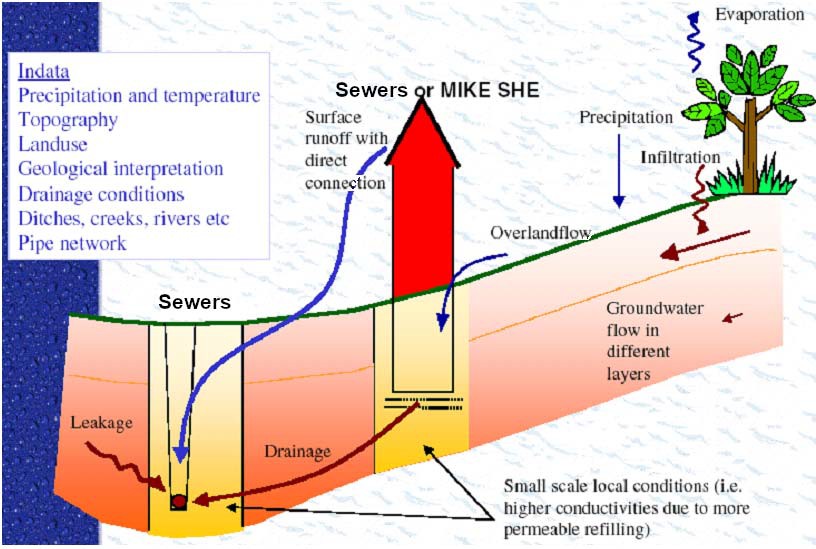
Figure 27.1 MIKE SHE to sewer coupling linkages
All exchange between sewers and MIKE SHE is calculated based on the following equation
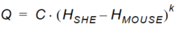
Equation 27.01
where - \(Q\) is the exchange between the sewer model and MIKE SHE, - \(C\) is the conductance,
k is a head difference exponent and
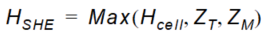
Equation 27.02
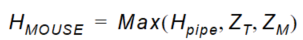
Equation 27.03
where - \(Hcell\) is the head in the MIKE SHE cell, - \(Hpipe\) is the head in the sewer pipe, - \(ZT\) is the topographic elevation in the cell - \(ZM\) is the elevation of the manhole.
There are five variations on how to calculate the exchange based on above equations:
- MIKE SHE SZ to Sewer model pipes: Pipe leakage approach
- MIKE SHE SZ to Sewer model pipes: Pipe leakage and SZ conductivity approach
- MIKE SHE SZ to Sewer model pipes: Pipe leakage and grouting conductivity approach
- MIKE SHE Overland flow to Sewer model open channels
- MIKE SHE Overland flow to Sewer model manholes
MIKE SHE SZ to Sewer model pipes
This is a leakage-based solution in which the head difference exponent is 1 and the conductance in Equation (33.1) for the flow to or from the pipe is calculated by
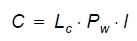
Equation 27.04
where - \(Lc\) is the leakage coefficient (see below), - \(Pw\) is the wetted perimeter for the flow (see below), - \(l\) is the length of the sewer pipe (link) in the MIKE SHE cell.
Leakage - The leakage can be defined in three ways.
Option 1 is the simple method, which is to use the specified pipe leakage coefficient.
Option 2 uses a combination of the pipe leakage coefficient and the aquifer hydraulic conductivity. In this case, the effective leakage coefficient is calculated as a series connection of the pipe leakage coefficient (Lp) and the “average” leakage coefficient of the aquifer grid cell (Laq). The average leakage coefficient of the grid cell is calculated assuming that the exchange of water between the pipe and the grid cell is both vertical and horizontal. The leakage coefficient calculation does not calculate a detailed flow path based on a geometric calculation, since a sewer pipe can be located anywhere in a grid cell. Instead, an average vertical and horizontal flow distance is used based on 1/4 of the vertical and horizontal cell dimensions. Thus,
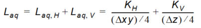
Equation 27.05
where - \(KH\) and \(KV\) are the horizontal and vertical hydraulic conductivities respectively - AUG \(xy\) and \(z\) are the horizontal and vertical cell dimensions.
The final leakage coefficient is then calculated as sum of the inverses of both the aquifer leakage coefficient and the pipe leakage coefficient, where the sum of the inverse leakages can be seen as a series of resistances:
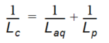
Equation 27.06
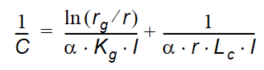
Option 3 accounts for pipe grouting with known thickness and conductivity, combined with the pipe leakage.
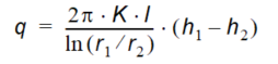
Equation 27.07
where - \(h1\) and \(h2\) are the heads at distances \(r1\), \(r2\) from the center of the radial flow, e. g. a bore hole. For a grouted pipe the grouting radius rg and the pipe radius r can be used for r1 and r2, and the aquifer head and the head in the pipe for h1 and h2.
A horizontal pipe may not be fully submerged in the groundwater. To account for this instead of \(2\pi\) the radial angle \(\alpha\) will be used which depends on the groundwater head and head in the pipe, similar to the wetted perimeter. It is calculated twice, once using the inner radius r and the water level h inside the pipe, and a second time using the outer radius and the ground water level, then the larger of the two values will be used:
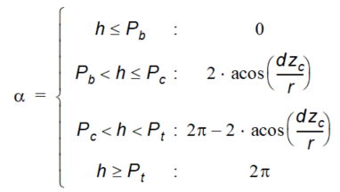
Equation 27.08
With Pb as the pipe (or grouting) bottom level, Pc as the pipe center level and Pt as the pipe (or grouting) top level. dzc is the vertical distance between the water level and the pipe center, positive in both directions.
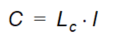
Equation 27.09
Kg is the hydraulic conductivity in the grouting zone, optionally it can be limited to
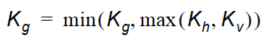
Equation 27.10
rg is the radius of the grouting zone and r is the radius of the pipe.
Wetted Perimeter - MIKE SHE uses the inner wetted perimeter if the flow is from the sewer to MIKE SHE. Whereas, it uses the outer wetted perimeter if the flow is from MIKE SHE to the sewer. The wetted perimeters are calculated by MIKE 1D.
MIKE SHE Overland flow to Sewer Model LINKS
If a MIKE 1D link is defined as link type CRS or Natural Channel and has a cross section which is "open", then MIKE SHE can exchange overland flow with it in both directions. In this case, the conductance in Equation (27.1) is defined as
Equation 27.11
where - \(Lc\) is the exchange coefficient - \(l\) is the length of the sewer pipe (link) in the MIKE SHE cell.
If the exponent Equation (27.1) is 1.0, then this is a simple drain formulation and the exchange coefficient is per length with units of [m/s]. If the exponent is 1.5, then this is a weir formulation and the units of the conductance term are [m1/2/s]. Generally, the unit of the exchange coefficient will be [m2-exponent/s] for pipes
MIKE SHE Overland flow to Sewer Model Manholes
If the sewer manholes are not sealed, then MIKE SHE can discharge overland flow into the sewer manholes. In this case, the exchange coefficient in Equation (27.1) is defined as

Equation 27.12
where - \(Lc\) is the exchange coefficient with units of [m2/s].
If the exponent Equation (27.1) is 1.0, then this is a simple drain formulation and the exchange coefficient, Lc, is per length with units of [m2/s]. If the exponent is 1.5, then this is a weir formulation and the units of the exchange coefficient are [m1.5/s]. Generally, the unit of the exchange coefficient will be [m2- exponent/s] for man holes.