Unsaturated Zone
1. Overview
There are three methods in MIKE SHE to calculate Unsaturated Flow:
- Richards Equation,
- the Gravity Flow, and
- the Two-Layer Water Balance.
The available options in this dialog and the items in the data tree depend on which UZ calculation method chosen in the Simulation Specification dialog.
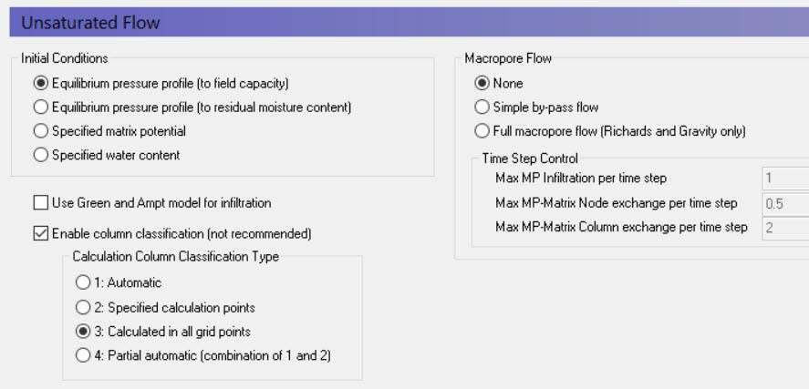
Initial Conditions
The initial conditions section defines the initial moisture content for the soil profile.
Equilibrium pressure profile (to field capacity) This is the default option. In this case, the initial soil moisture distribution follows the water content-pressure relationship from the soil database with a minimum water content equal to the calculated field capacity. In other words, the profile will be saturated at the water table and decrease above the water table until field capacity is reached. All cells above this will have a water content equal to field capacity. This is a reasonable initial condition for most temperate climates, where the water content is regularly recharged by rainfall. Generally, this will lead to an initial drainage from the UZ as the water content equilibrates with the rainfall rate.
Equilibrium pressure profile (to residual moisture content) This option is useful in arid and semi-arid conditions where the natural soil moisture below the root zone is low. When the rate of rainfall is low, then the natural soil moisture distribution will approximate the soil-moisture pressure curve. This option is useful in dry conditions because drainage to dry soil moisture with depth may require a long simulation to reach equilibrium.
Specified matrix potential and Specified water content These two options for specifying the water content or matrix potential with depth are typically only used in special conditions where the models are very detailed and accurate soil moisture or pressures have been measured. For example, in column experiments. Specifying these values requires you to define either a uniform value, or values and specified depths.
Green and Ampt Infiltration
The Green and Ampt infiltration is an analytical solution to the increased infiltration experienced in dry soils due to capillarity. It is available for the 2-Layer WB and the Gravity Flow UZ solution methods. The Richards equation method already includes capillarity so the Green and Ampt method is not applicable.
Enable column classification
The column classification should be avoided today because the models have become more complex, MIKE SHE has become more efficient, and computers have become faster.
If the either Richards Equation or the Gravity Flow Module are chosen for calculating the unsaturated zone flow, then the top-level Unsaturated Zone dialogue has an option to turn open a section for the column classification. However, if the Two Layer Method is chosen then the Column Classification section is unavailable.
Calculating unsaturated flow in all grid squares for large-scale applications can be time consuming. To reduce the computational burden MIKE SHE allows you to compute the UZ flow in a reduced subset of grid squares. The subset classification is done automatically by the pre-processing program according to soil and, vegetation distribution, climatic zones, and depth to the groundwater table.
Column classification can decrease the computational burden considerably. However, the conditions when it can be used are limited. Column classification is either not recommended or not allowed when:
- the water table is very dynamic and spatially variable because the classification is not dynamic,
- if the 2-layer UZ method is used because the method is fast and the benefit would be limited,
- if irrigation is used in the model because irrigation zones are not a classification parameter, and
- if flooding and flood codes are used, since the depth of ponded water is not a classification parameter
If the classification method is used, then there are three options for the classification:
Automatic classification
The automatic classification requires a distribution of groundwater elevations (see Groundwater Depths used for UZ Classification). This can be either the initial depth to the groundwater based on the initial heads, or you can supply a .dfs2 map of the groundwater elevations. In both cases, you must supply a table of intervals upon which the classification will be based. The number of computational columns depends on how narrow the intervals are specified. If, for example, two depths are specified, say 1 m and 2 m, then the classification with respect to the depth to groundwater will be based on three intervals: Groundwater between 0 m and 1 m, between 1 m and 2 m, and deeper than 2 m.
If the Linear Reservoir method is used for the groundwater, then the Interflow reservoirs are also used in the classification. However, since feedback to the UZ only occurs in the lowest Interflow reservoir of each subcatchment, the Interflow reservoirs are added to the Automatic Classification in two zones - those that receive feedback and those that don’t.
Specified classification
Alternatively a data file specifying Integer Grid Codes, where UZ computations are carried out can be specified, with grid codes range from 2 up to the number of UZ columns (see Specified classification. The location of the computational column is specified by a negative code and the simulation results are then transferred to all grids with an equivalent positive code.
Calculated in all Grid points (default)
For smaller scale studies, or studies where the classification system becomes intractable, you can specify that computations are to be carried out in all soil columns.
Partial Automatic
Finally, a combination of the Automatic classification and the Specified classification is available. If this option is chosen an Integer Grid Code file must be provide (see Partial automatic classification) with the following grid codes: In grid points where automatic classification should be used the grid code 1 must be given. In grid points where computation should be performed for all cells the grid code 2 must be given.
Macropore Flow
Flow through macropores in unsaturated soil is important for many soil types.
Simple bypass flow - A simple empirical function is used to describe simple bypass flow in macropores. The infiltration water is divided into one part that flows through the soil matrix and another part, which is routed directly to the groundwater table, as bypass flow.
The bypass flow is calculated as a fraction of the net rainfall for each UZ time step. The actual bypass fraction is a function of a user-specified maximum fraction and the actual water content of the unsaturated zone, assuming that macropore flow occurs primarily in wet conditions.
Typically, macropore flow is highest in wet conditions when water is flowing freely in the soil (e.g. moisture content above the field capacity, \(\theta_{FC}\)) and zero when the soil is very dry (e.g. moisture content at the wilting point, \(\theta_{WP}\))
Simple bypass flow is described in the Reference section under Simplified Macropore Flow (bypass flow).
Full Macropore Flow - Macropores are defined as a secondary, additional continuous pore domain in the unsaturated zone, besides the matrix pore domain representing the microporous bulk soil. Macropore flow is initiated when the capillary head in the micropore domain is higher than a threshold matrix pressure head, corresponding to the minimum pore size that is considered as belonging to the macropore domain. Water flow in the macropores is assumed to be laminar and not influenced by capillarity, thus corresponding to gravitational flow.
Full Macropore flow is described in the Reference section under Full Macropore Flow.
Max macropore infiltration per time step - This is a stability criterion that prevents too much water from entering the macropores in one time step.
Max macropore matrix exchange per time step - This is a stability criterion that prevents too much water from exchanging between the macropores and the bulk matrix in one node in one time step.
Max macropore-matrix column exchange per time step - This is a stability criterion that prevents too much water from exchanging between the macropores and the bulk matrix in the entire column in one time step.
Related Items:
- Unsaturated Zone - Technical Reference
- Richards Equation
- Gravity Flow
- Two-Layer Water Balance
- Green and Ampt Infiltration
- Simplified Macropore Flow (bypass flow)
- Full Macropore Flow
- Coupling the Unsaturated Zone to the Saturated Zone
2. Soil Profile Definitions
| Soil Profile Definitions | |
|---|---|
| Conditions | when Unsaturated Flow selected in the Simulation Specification dialogue and Richards Equation or the Gravity Flow module selected for the numeric engine |
| dialogue Type | Integer Grid Codes with sub-dialogue data |
| EUM Data Units | Grid Code |
The first part of the soil profile definition is to define the areas with the same soil profiles. This can be done using either a uniform value or distributed using a dfs2 integer grid code file or a polygon .shp file. For each unique grid code or polygon in the distribution file, a separate sub-item will appear in the data tree, in which you can define the soil profile data.
In the sub-item dialogues, the soil type and distribution of the soil layers (i.e. depth and thickness of each soil type) in the individual profiles is specified, as well as the vertical discretisation of the soil profile.
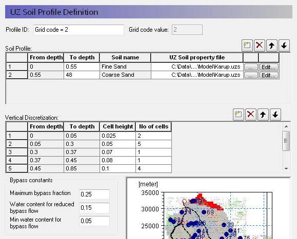
Definition of soil properties
Profile ID - This is the editable name displayed in the data tree for this profile.
Grid code value - This is the current integer grid code or polygon value read from the soil distribution.
Soil Profile - The soil profile section allows you to define the vertical soil profile. Soil layers can be added, deleted and moved up and down using the icons.
From and To Depths refers to the distances to the top and bottom of the soil layer, below the ground surface. Only the To Depth item is editable, as the From Depth item is equal to the bottom of the previous layer.
Soil name is the name of the soil selected in the UZ Soil Property file. It is not directly editable but must be chosen from the list of available soil names when you assign the UZ Soil property file using the file browser.
UZ Soil property file is the file name of the soil database, in which the soil definition is available. The Edit button opens the specified Soil property database file, whereas the Browse button [...] opens the file browser to select a file.
Vertical discretisation - In this section you specify the vertical discretisation of the soil profile, which typically contains small cells near the ground surface and increasing cell thickness with depth. However, the soil properties are averaged if the cell boundaries and the soil boundaries do not align.
From and To Depths refers to the distances to the top and bottom of the soil layer, below the ground surface. Neither are directly editable since they are calculated from the number of cells and their thicknesses.
Cell Height is the thickness of the numerical cells in the soil profile.
No. of Cells is the number of cells with the specified cell height. Together these two values define the total thickness of the current section.
Dispersivity is the longitudinal dispersivity in the column. This column only appears if WQ is simulated in the unsaturated zone.
The discretisation should be tailored to the profile description and the required accuracy of the simulation. If the full Richards equation is used the vertical discretisation may vary from 1-5 cm in the uppermost grid points to 10-50 cm in the bottom of the profile. For the Gravity Flow module, a coarser discretisation may be used. For example, 10-25 cm in the upper part of the soil profile and up to 50-100 cm in the lower part of the profile.
Note
At the boundary between two blocks with different cell heights, the two adjacent boundary cells are adjusted during the preprocessing to give a smoother change in cell heights.
Bypass Constants The bypass constants are editable when Simple Bypass flow is checked on in the main Unsaturated Zone dialogue. The available bypass parameters include:
Maximum bypass fraction - This is the maximum fraction of net rainfall that will infiltrate via simple macropore flow. Valid values are between 0 and 1.0.
Water content for reduced bypass flow - This is the threshold water content below which the bypass fraction is reduced. If the water content 10cm or 50cm below the ground surface is less than this water content, then the soil is dry, and the bypass flow will be reduced.
Limit on water content for bypass flow - This is the minimum water content for bypass flow. If the water content 10cm or 50cm below the ground surface is less than this limit, then the soil is very dry, and the bypass flow will be zero.
The actual relationship between the bypass constants and the calculation of the bypass flow is described in Simplified Macropore Flow (bypass flow).
Related Items:
3. Mass Transfer Coefficient to Unsaturated Macropores
| Mass transfer coefficient to unsaturated macropores | |
|---|---|
| Conditions | when water quality for Unsaturated Flow is selected in the Water Quality Simulation Specification dialogue and Full Macropore Flow is selected in the main Unsaturated Flow dialog |
| dialogue Type | Stationary Real Data |
| EUM Data Units | 1st-order rate WQ model [e.g. 1/day] |
Macropores are defined as a secondary, additional continuous pore domain in the unsaturated zone, besides the matrix pore domain representing the microporous bulk soil.
In other words, the macropores represent a continuous secondary porous media that is “parallel” to the soil matrix porosity. Mass transfer to macropores occurs mostly by means of diffusion from the unsaturated zone soil matrix.
This coefficient represents the rate of transfer from the soil matrix to the macropores. It is defined per species.
Related Items:
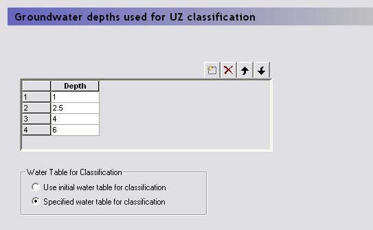
4. Groundwater Depths used for UZ Classification
| Groundwater Depths used for UZ Classification | |
|---|---|
| Conditions | if either the Automatic or Partially automatic column classifications selected in the main Unsaturated Zone dialogue |
The automatic or partially automatic classification requires a distribution of groundwater elevations (see the main Unsaturated Zone dialogue). This can be either the initial depth to the groundwater based on the initial heads (default option), or you can supply a .dfs2 map of the groundwater elevations (second option). If you chose the second option, then a new item, Ground Water Table for UZ classification, will appear in the data tree.
In both cases, you must supply a table of intervals upon which the classification will be based. The number of computational columns depends on how narrow the intervals are specified. If, for example, two depths are specified, say 1 m and 2 m, then the classification with respect to the depth to groundwater will be based on three intervals: Groundwater between 0 m and 1 m, between 1 m and 2 m, and deeper than 2 m.
Related Items:
5. Ground Water Table for UZ classification
| Groundwater table for UZ classification | |
|---|---|
| Conditions | if Specified water table for classification selected in the Groundwater Depths used for UZ Classification dialogue |
| dialogue Type | Stationary Real Data |
| EUM Data Units | Elevation or Height above ground |
If the Specified water table for classification is selected in the Groundwater Depths used for UZ Classification dialogue, then this is the ground water table used for the classification.
Related Items:
6. Partial automatic classification
| Partial Automatic Classification | |
|---|---|
| Conditions | if the Partially automatic column classifications selected in the main Unsaturated Zone dialogue |
| dialogue Type | Integer Grid Codes |
| EUM Data Units | Grid Code |
| Valid Values | 1 or 2 |
A combination of the Automatic classification and the Specified classification is available. If this option is chosen an Integer Grid Code file must be provide with the following grid codes:
- In grid points where automatic classification should be used the grid code must be 1.
- In grid points where computation should be performed for all cells the grid code must be 2.
Related Items:
Lumped UZ Calculations (Column Classification)
7. Specified classification
| Specified Classification | |
|---|---|
| Conditions | if Specified classification selected in the main Unsaturated Zone dialogue |
| dialogue Type | Integer Grid Codes |
| EUM Data Units | Grid Code |
| Valid Values | +/- 2 to the number of SZ cells (-1, 0, 1 not valid) |
This is a data file specifying Integer Grid Codes, where UZ computations are to be carried out. Grid codes range from 2, up to the number of UZ columns. The location of the computational column is specified by a negative code and the simulation results are then transferred to all grids with an equivalent positive code.
For example, if a grid code holds the value -2, a UZ computation will be carried out for the profile located in that grid. Simulation results will subsequently be transferred to all grid codes with code value +2.
An easy way to generate a .dfs2 file to be used for specification of UZ computational columns is to let the MIKE SHE setup program generate an automatic classification first and subsequently extract the UZ classification grid codes. The extracted .dfs2 file can be edited in the 2D editor as desired and used to specify UZ computational grids.
Related Items:
8. 2-Layer UZ soil properties
| 2-Layer UZ Soil Properties | |
|---|---|
| Conditions | when Unsaturated Flow selected in the Simulation Specification dialogue and the Two-Layer Water Balance method selected for the numeric engine |
| dialogue Type | Integer Grid Codes with sub-dialogue data |
| EUM Data Units | Grid Code |
The first part of the soil definition is to define the areas with the same soil profiles. This can be done using either a uniform value or distributed using a dfs2 integer grid code file or a polygon .shp file. For each unique grid code or polygon in the distribution file, a separate sub-item will appear in the data tree, in which you can define the soil profile data.
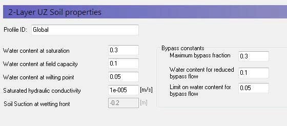
Definition of soil properties
Profile ID - This is the editable name displayed in the data tree for this profile.
Grid code value - This is the current integer grid code or polygon value read from the soil distribution.
Water content at saturation - This is the maximum water content of the soil, which is usually approximately equal to the porosity,
Water content at field capacity - This is the water content at which vertical flow becomes negligible. In practice, this is the water content that is reached when the soil can freely drain. Although, it is usually higher than the residual saturation, which is usually defined as the minimum saturation that can be achieved in a laboratory test.
Water content at wilting point - This is the lowest water content that plants can extract water from the soil.
Saturated hydraulic conductivity - The saturated hydraulic conductivity of the soil is equal to the maximum infiltration rate of the soil.
Soil suction at wetting front - The soil suction at the wetting front is used in the Green and Ampt infiltration model to increase the infiltration rate beyond the saturated hydraulic conductivity when the soil is dry. This is a soil specific value that accounts for the capillarity of the soil.
Bypass Constants The bypass constants are editable when Simple Bypass flow is checked on in the main Unsaturated Zone dialogue. The available bypass parameters include:
Maximum bypass fraction - This is the maximum fraction of net rainfall that will infiltrate via simple macropore flow. Valid values are between 0 and 1.0.
Water content for reduced bypass flow - This is the threshold water content below which the bypass fraction is reduced. If the water content 10cm or 50cm below the ground surface is less than this water content, then the soil is dry, and the bypass flow will be reduced.
Limit on water content for bypass flow - This is the minimum water content for bypass flow. If the water content 10cm or 50cm below the ground surface is less than this limit, then the soil is very dry, and the bypass flow will be zero.
The actual relationship between the bypass constants and the calculation of the bypass flow is described in Simplified Macropore Flow (bypass flow).
Related Items:
- Unsaturated Zone - Technical Reference
- Two-Layer Water Balance
- Simplified Macropore Flow (bypass flow)
9. ET Surface Depth
| ET Surface Depth | |
|---|---|
| Conditions | when Unsaturated Flow selected in the Simulation Specification dialogue and the Two-Layer Water Balance method selected for the numeric engine |
| dialogue Type | Stationary Real Data |
| EUM Data Units | Depth below ground |
In unsaturated soils, capillary action can lead to saturated conditions existing some distance above the water table. If the water table is close to the ground surface, ET will continue to occur at the maximum rate, so long as this capillary zone reaches the ground surface. That is, evapotranspiration will not decrease the saturation but draw water directly from the water table due to capillary action. Similarly, when the water table is deeper, plant roots will draw water directly from the saturated zone as long as the roots reach the capillary zone.
In MIKE SHE, the ET surface depth is the thickness of the capillary fringe. This thickness is added to the root depth to define the thickness of Layer 1 in the Two-Layer Water Balance ET/UZ method.
In the absence of vegetation, if the water table is above this depth, then soil evaporation will draw water from the water table (SZ). However, the rate that it can remove water from the water table decreases linearly with depth. That is, if the water table is at the ground surface it will remove water at the full rate and if the water table is at the ET Surface Depth then the rate will go to zero.
This is exactly the same function as MODFLOW, except MODFLOW does not describe it like this. In MODFLOW, because there is no vegetation, MODFLOW users typically use the linear function to also “simulate” root zone ET.
In MIKE SHE, if vegetation is present then the exact same function is used, but instead of being relative to the soil surface, it is relative to the bottom of the root zone. If the water table is at or above the bottom of the root zone, then ET will be removed from SZ at the full rate. As the water table falls below the root zone, ET from SZ will be reduced linearly until the water table is at distance below the root zone equal to the ET Surface depth – at which point the ET from SZ becomes zero.
Note, that Layer 1 in the 2-Layer Water Balance UZ/ET method is the thickness of the root zone plus the ET Surface depth. If the water table falls below the bottom of the Layer 1, then ET from the SZ will stop. This does not mean that ET stops. ET will continue to remove water from the available water in Layer 1. However, Layer 1 is greater than the root zone thickness, which means that the available storage is increased by the thickness of the ET Surface Depth. This is probably not significant when the root zone is thick relative to the thickness of the capillary fringe. However, if the capillary fringe is thick, say more than 1m in a silty-clay, then the amount of water available in Layer 1 may be artificially high.
Richards equation, there is no ET Surface depth, because the capillary thickness is defined by the Sat-Pressure curve. In the Gravity method, the capillarity is ignored.
In coarse to medium sands, the ET surface depth is typically less than 10cm. In fine sands and silts, the ET surface depth could be a half a metre or more.
Note
The ET surface depth must be greater than or equal to zero.
Related Items:
10. Initial Conditions (UZ)
| Initial conditions for the unsaturated zone | |
|---|---|
| Conditions | when Unsaturated Flow selected in the Simulation Specification dialogue AND either The Water Quality is turned on for the unsaturated zone, OR An initial pressure or saturation has been selected for the Richards/Gravity flow solution method |
| dialogue Type | Stationary Real Data |
| EUM Data Units | Elevation or Concentration or Temperature |
There are two different initial conditions for the unsaturated zone.
Water movement - For water flow in the unsaturated zone (Richards/Gravity methods only), the initial conditions can be defined to be in equilibrium, which means the initial pressure head and water content are derived from the soil pressure-moisture content relationship, or you can specify a water content or water pressure directly. The choice of initial condition is defined in the main Unsaturated Zone dialogue.
Water quality - For the water quality module, an initial concentration is required for each mobile and sorbed species. Furthermore, if temperature dependent decay is specified, then an initial soil temperature must also be specified.
The initial conditions for the unsaturated zone can be defined as a constant value, or by layer, or from a fully 3D dfs3 file.