Water Balance Editor
The water balance utility is a flexible, post-processing tool for generating water balance data for MIKE SHE simulations. Output from the water balance utility can include area normalized flows (storage depths), storage changes, and model errors resulting from convergence problems. Water balance data can be generated at a variety of spatial and temporal scales and in a number of different formats.
To extract the water balance data, you must specify which simulation you are going, then specify the area of your model that you want the water balance for, and, finally, extract the MIKE SHE water balance data from the results files.
Once you have created a new water balance document, the following three tabs will be displayed
Related items
1. Extraction
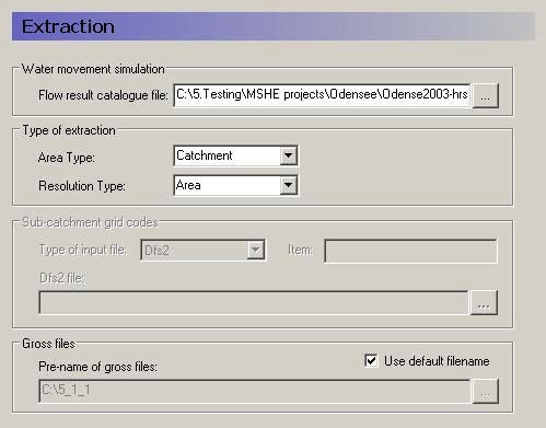
Flow result catalogue file
A MIKE SHE simulation generates various output files depending on the options and engines selected for the MIKE SHE simulation. The .sheres file is a catalogue of all the various output files generated by the current MIKE SHE run. When you select the .sheres file, you are not specifying the particular output, but actually just a set of pointers to all the output files.
The extraction process reads all of the output files and makes itself ready to produce specific water balances. In the extraction dialogue, you specify the .sheres file for the simulation that you wish to calculate the water balance for. The .sheres file is located in the same directory as your results.
Note
Although, this is an ASCII file, you should be careful not to make any changes in the file, or you may have to re-run your simulation.
Type of Extraction
You can choose to calculate the water balance on the entire model domain or in just a part of the domain. By default the calculation is for the entire domain, or catchment. If you choose the subcatchment area type, they you will be able to use a dfs2 integer grid code file to define the areas that you want individual water balances for.
If you use an area resolution, then the water balance will be a summary water balance for either the entire catchment or the sub-areas that you define.
If you use a single-cell resolution, you will be able to generate dfs2 maps of the water balance.
Sub-catchment grid codes
The subcatchment integer grid code file is only used if you have selected the sub-catchment water balance type. You can specify a delete value to exclude areas from the water balance. The grid spacing and dimensions in this dfs2 file must match exactly the model grid.
You can also specify a polygon shape file to define the sub-catchment areas. The shape file may contain multiple polygon, with the same or different codes. Further, the shape file length units do not have to be the same as the model length units (e.g. feet vs. meters).
Gross files
The pre-processor extracts the water balance data from the standard MIKE SHE output files and saves the data in a set of “gross” files. The file names of the gross files is built up from the project name and prefix specified here. The default value is normally fine.
Related items
2. Postprocessings
After you have extracted the water balance data from the MIKE SHE results files, then you can switch to the post-processing tab. Here you can create any number of individual water balances by simply clicking on the Add item icon and specifying the water balance parameters in the parameter dialogue.
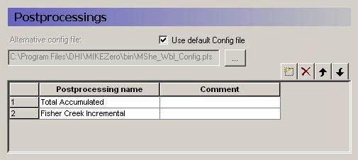
A single Postprocessing item is created by default when the water balance file is created. The default Postprocessing name can be change to a more appropriate name. Postprocessing items that are no longer needed can be deleted using the Delete button.
Use default Config file
Unchecking the Use default Config file checkbox, allows you to specify the location of a custom water balance Config file. Development of custom water balance configuration files is described in detail in Making Custom Water Balances.
Related items
2.1 Postprocessing Detail
For each item in the Postprocessing list above, a new item will be added to the data tree. If you expand the data tree, each will have the following dialogue.
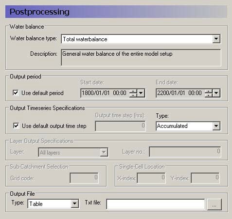
Water Balance
Multiple postprocessings can be run on each water balance extraction. More detail on the types of available water balances data are discussed in the Standard Water Balance Types section. In brief, the available types include
- The total water balance of the entire model catchment or sub-catchments in an ASCII table, a dfs0 file, a dfs2 map file, or a graphical chart (also by layer),
- Model errors for each hydrologic component (overland, unsaturated zone, etc.) in an ASCII table, a dfs0 file, or a dfs2 map file (also by layer),
- The snow melt and canopy/interception water balance in an ASCII table, or a dfs0 file,
- An abbreviated or detailed water balance for overland or unsaturated flow in an ASCII table, or a dfs0 file, and
- An abbreviated or detailed water balance by layer for saturated flow in an ASCII table, or a dfs0 file.
Output Period
An output period different from the total simulation period can be specified by unchecking Use default period and setting the Start date and End date to the period of interest
Output time series Specification
Incremental or Accumulated water balances can be calculated. An incremental water balance is calculated (summed) for each output time step in the Output period. An accumulated water balance each output time step is accumulated over the Output period
Layer Output Specifications
If you are using water balance types that calculate data on a layer basis, you can specify whether you want All layers or just the Specified layer, where you also must specify a layer number.
Sub-catchment Selection
If you extracted sub-catchment data from the WM results, then you must specify a subcatchment number or the name of the polygon for which you want the water balance for. The combobox contains a list of valid ID numbers or polygon names.
Single Cell Location
If you extracted the WM data by cell, then if you are not creating a map output, then you have to specify a cell location for which you want a water balance.
Output File
If you are creating a table or time series water balance, then you can write the output to either a dfs0 file or to an ASCII file for import to MSExcel, or other post-processing tool. If you are creating a map, then the output will be to a dfs2 file, with the same grid dimensions and spacing as the model grid. If you are creating a chart, then the output will be written to an ASCII file, with a special format for creating the graphic.
Related items
3. Results
The data tree for the results tab lists all of the calculated water balances. The dialogue for each item, includes the file name and an Open button, that will open an editor for the file. For ASCII output, this will be your default ASCII editor - usually Notepad. For dfs0 and dfs2 files, the DHI Time Series Editor or Grid Editor will be opened. For the chart output, the graphic will be displayed by the program WblChart.