Particle Tracking (PT)
The PT module calculates the flow path of a hundreds, thousands, or even millions, of hypothetical particles, which are moved in the three-dimensional, saturated groundwater zone (SZ). The particles are displaced individually in a number of time steps. The movement of each particle is composed of a deterministic part, in which the particle is moved according to the local groundwater velocity calculated by the MIKE SHE water movement (WM) module, and a stochastic part where the particle is moved randomly based on the local dispersion coefficients.
Particle tracking is only calculated for the saturated zone (SZ) and particles that leave SZ are not traced any further. Initially, the user assigns a number of particles to each model grid cell. Particles are added during the simulation from sources, for example solutes in precipitation or from boundary or internal defined concentration cells. Particles leave SZ when they arrive at a boundary or an internal constant concentration cell or when they go to a sink. Possible sinks in the Particle Tracking are wells, rivers, drains, and exchange with the unsaturated zone or overland flow.
All particles are assigned a mass, which means that a number of particles within a specific volume correspond to a solute concentration. The Particle Tracking module can therefore be used for solute transport simulations and is in some cases superior to the conventional numerical solution of the advection-dispersion equation since numerical dispersion is negligible. However, the module is mostly used for delineation of abstraction well capture zones and upstream zones and for determination of groundwater age and conservative solute transport times.
The PT module uses the concept of 'registration' cells. This records particle data when particles enter certain model cells. Registration can be used to delineate capture zones or to observe particles passing through some region of interest, such as a redox layer.
1. Requirements in MIKE SHE WM
Prior to running a PT simulation, the MIKE SHE Water Movement (WM) simulation must be run. This section describes what needs to be specified in the WM simulation to run the PT simulation afterwards.
a. Flow Storing Requirements
Particle transport calculations in MIKE SHE PT are based on the groundwater flows from a MIKE SHE WM simulation. In principle, only groundwater fluxes are needed but to ensure that all the needed WM result data types are stored the user has to specify that results should be stored for an AD run in the WM input. Thus, you must check the appropriate checkbox under “Storing of Results” in the MIKE SHE WM GUI.
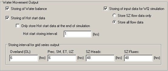
The user can choose between “SZ only” and “All hydraulic components”, however, for PT-simulations “SZ only” will be sufficient, since particle tracking is only calculated for the saturated zone.
The simulated particle distribution is stored with a desired frequency in the MIKE SHE WM GUI under “Storing of results” => “Grid series output”. It is important that the SZ and SZ-flow use the same storing frequency in order to run the following PT simulation. The WM result files to be used in the PT-simulations will be located in a folder with the same name as the *.SHE file.
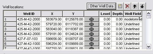
b. Specification of Well Fields
To be able to retrieve particle locations based on well fields, it is necessary to specify the well fields in the MIKE SHE well database file.
2. Output from the PT simulations
The result files will be located in standard Results directory for your project. The PT result files are:
- projectname.PTRES: An ASCII file in pfs-format listing the abstraction wells and the computational cells, where abstraction occurs. Used for retrieval of particle location - see PT Registration Extraction.
- projectname.PTREG and projectname.trf: Two binary files that cannot be opened directly.
- projectname.PTBIN: An optional binary file containing all of the particle locations at every saved time step. Individual path lines can be extracted using the Extraction of Particle Path Lines.
- projectname.PTGross.shp: An optional point theme shape file containing the path line information of every particle at every saved time step. As part of the shape file, a .shx and a .dbf file are also created. The .dbf file can be opened in e.g. Microsoft Excel if it does not exceed the maximum possible number of lines.
Table 41.1 Fields in \<projectname>_PTGross.dbf
| Field Name | Unit | Description |
|---|---|---|
| ID | - | Particle ID |
| X | As model coordinates | Location in x direction |
| Y | As model coordinates | Location in y direction |
| Z | As model coordinates | Location in z direction |
| IX | Cell index | Cell in x direction |
| IY | Cell index | Cell in y direction |
| Layer | Layer index | Cell in z direction |
| Reg code | - | ‘Undefined’, int code, ‘Incell containing Well’, blank |
| Sink/Other | - | Sink description |
| Well ID | - | ID of the well (sink) |
| Well Field | - | ID of the well field (sink) |
| Branch name | - | Name of the river branch (sink) |
| Chain* | (length) | Chainage in the river branch (sink) |
| Time stamp | date/time | Registration time |
| Ttotal* | (time span) | Time since start of simulation |
| dBirth* | (time span) | Time since particle entered simulation |
| dTlnc* | (time span) | Time since particle has last been registered |
| PathLen* | (length) | Length of particle path since start of simulation |
| dPth_Len* | (length) | Length of particle path since has last been registered |
- Output in user units, name of unit added to field name. As the length of shp fields is limited to 10 truncation may occur
- projectname_AD_3DSZ.dfs3: Temporal and spatially varying SZ concentrations in the mobile phase based on the mass of the particles.
- projectname_PT_3DSZ.dfs3: Temporal and spatially varying PT results including:
- Number of particles - this is the actual number of particles in each cell
- Accumulated particle count – this is the number of particles that have entered the cell during the simulation
- Number of registered particles – this is the number of particles that started in this cell that have become registered
- Most recent registration zone – this is the registration zone attached to the last particle to be registered that originated in the cell
- Average age – this is the average age of all the particles in the cell
- Average transport time – this is the average length of time from when the particle was born in this cell until it was registered somewhere
Besides these result files, the program also writes output to two log files. The error log list errors encountered during execution and the print log file contains execution step information, statistics on the run and a mass balance (if requested).
3. Extraction of particle registrations
a. Introduction
After the particle tracking has been run, the registration information needs to be read from the output files and processed in a useful way. The Results Tab includes an utility to sift through all the particles and their registrations, to find the ones that you want. This is output from this utility is an ArcGIS point-theme, shape file with the starting locations of the all the particles that meet your registration criteria. The extraction utility allows your to filter the results for:
- Destination type:
- Specific sink types (drain, river, unsaturated zone, well, constant concentration boundary or constant concentration sink)
- Registration codes specified by the user
- Wells found in the flow results
- Well fields found in the flow results*)
- Layer from which the particles originated
- Release (birth) time
- Transport time
Note
To extract particle locations based on well fields requires that different well fields have been defined, see section Specification of Well Fields.
The results can be written to either - a single shape file where the point attributes allow further selection of the particles in ArcView, or - separate files for each destination type and optionally for each layer e.g. one file for each sink type/layer combination.
More detailed information on the actual extraction mechanics can be found in the PT Registration Extraction section.
b. Running from a batch file
The registration extraction can be run from a command line. To execute the program open a command line and type:
Ptoutputretrieval.exe *projectname.she extraction_num*
The extraction_num is the item number in the table of extraction items in the PT Registration Extraction dialogue. The extraction will proceed silently - that is without any messages. To run the extraction with the messages, you need to use
MZLaunch *project_name.she* -e Ptoutputretrieval.exe
which will start the MZLaunch utility
projectname_ptoutputretrieval.err: If errors occur during execution of the program these are written to this log file.
c. Limitations with the PT registration method
When using registration zones to identify particles that move through certain parts of the model it should be noted that particles can appear more than once in the output. As they move from one zone to the next they are repeatedly registered and are finally also registered when they are removed from the model by a sink. An example would be a particle moving into a registration zone with code 1. The particle is then registered as being in an 'active cell' and the registration zone code and travel time to this zone is memorised. If the particle is at a later time removed by a well it will again be registered but now it will be registered as being removed by the 'Well' sink.
If there are multiple wells within one cell and output for wells is requested then the output can contain the same particle more than once. As the model does not know which of the wells the particle should be assigned to (the program looks at the total well sink for the cell and cannot distinguish individual wells) the particle will be repeated for each of the wells within the cell.
4. Extraction of Particle Path Lines
It is too cumbersome to extract and plot the path lines for all of the thousands of particles that can be generated during a PT simulation. The PT Path line Extraction utility allows you to extract the path lines for specific particles if you have saved the intermediate locations in the Storing of Results dialogue.
To extract a particle path line you need a Particle ID. These can only be found after the simulation by evaluating the PT output. For example, you can find the particle ID by extracting the particle start locations that end in a specific well and then finding the ID numbers of the particles that you want in the shape file that was created.
In the Results tab, the PT Pathline Extraction utility is available to make this extraction.
Running from a batch file
The path line output retrieval program can be run from a command line. To execute the program, open a command line and type:
PtBinRetrieval.exe file_name.she extraction_num
The extraction_num is the item number in the table of extraction items in the PT Pathline Extraction dialogue. The extraction will proceed silently - that is without any messages. To run the extraction with the messages, you need to use
MZLaunch file_name.she -e PtBinRetrieval.exe
which will start the MZLaunch utility. Particle IDs can be found by using the PT Output Retrieval utility.