Numerical Layers
1. Specific Yield of the upper SZ numerical layer
The specified value for specific yield is not used for the specific yield of the upper most SZ numerical layer if UZ is included in the simulation.
By definition, the specific yield is the amount of water release from storage when the water table falls. The field capacity of a soil is the remaining water content after a period of free drainage. Thus, specific yield is equal to the saturated water content minus the field capacity.
To avoid water balance errors at the interface between the SZ and UZ models, the specific yield of the top SZ layer is set equal to the he saturated water content minus the field capacity. The value is determined once at the beginning of the simulation. The water content parameters are taken from the UZ layer in which the initial SZ water table is located.
In principle, having different values between the SZ and UZ models does not directly cause a water balance error, but it may cause numerical problems that could lead to water balance errors. By definition, the steady-state water table location will be identical in both the SZ and UZ models. Pumping from the SZ will lower the SZ water table by an amount equal to the specific yield divided by the cell area times the pumping rate. However, if the field capacity is not correlated to the specific yield, then the amount of water released from storage in the UZ will be more or less than the amount extracted from the SZ cell. This will result in different water tables in the SZ and UZ models. If pumping stops, the system will again reach an equilibrium with the same water table in both the SZ and UZ simply because of the pressure head redistribution.
As mentioned, the upper Sy value is calculated only at the beginning of the simulation based on the UZ layer in which the initial SZ water table is located. If the soil profile has multiple soil types with different field capacities and saturated water contents, then the specific yield in the SZ and UZ model may diverge during the simulation. With slowly moving water tables, the differences may not be that large and the errors generated will likely be tolerable. If the water table drops into a lower SZ layer, then the specified Specific Yield will be used.
The actual value used in the model is displayed in the pre-processed tab under Specific Yield.
2. SZ Boundary Conditions
The upper boundary of the top layer is always either the infiltration/exfiltration boundary, which in MIKE SHE is calculated by the unsaturated zone component or a specified fraction of the precipitation if the unsaturated zone component is excluded from the simulation.
The lower boundary of the bottom layer is always considered as impermeable.
In MIKE SHE, the rest of the boundary conditions can be divided into two types: Internal and Outer. A boundary condition in one of the cells on the edge of the model domain is an “outer boundary”. All other boundary conditions inside the domain are called “internal boundaries”.
3. Groundwater Drainage
a. Overview
Saturated zone drainage is a special boundary condition in MIKE SHE used to defined natural and artificial drainage systems that cannot be defined in the river model.
Saturated zone drainage is removed from the layer of the Saturated Zone model containing the drain level. Water that is removed from the saturated zone by drains is routed to local surface water bodies, local topographic depressions, or out of the model.
When water is removed from a drain, it is immediately moved to the recipient. In other words, the drain module assumes that the time step is longer than the time required for the drainage water to move to the recipient. This is the same as a “full pipe”. That is, water added to the end of a full pipe of water causes an equal amount of water to immediately flow out the opposite end - regardless of the length of the pipe.
Drain flow is simulated using an simple linear reservoir formula. Each cell requires a drain level and a time constant (leakage factor). Both drain levels and time constants can be spatially defined. A typical drainage level is 1m below the ground surface and a typical time constant is between 1e-6 and 1 e-7 1/s.
Drainage reference system
MIKE SHE also requires a reference system for linking the drainage to a recipient node or cell. The recipient can be a river model node, another SZ grid cell, or a model boundary.
There are four different options for setting up the drainage source-recipient reference system
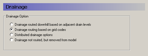
Drainage routed downhill based on adjacent drain levels
This option was originally the only option in MIKE SHE. The reference system is created automatically by the pre-processor using the slope of the drains calculated from the drainage levels in each cell.
Thus, the pre-processor calculates the drainage source-recipient reference system by
- looking at each cell in turn and then
- looking for the neighbouring cell with the lowest drain level.
- If this cell is an outer boundary cell or contains a river link, the search stops.
- If this cell does not contain a boundary or river link, then the search is repeated with the next downstream neighbour until either a local minimum is found or a boundary cell or river link is found.
The result of the above search from each cell is used to build the source- recipient reference system.
If local depressions in the drainage levels exist, the SZ nodes in these depressions may become the recipients for a number of drain flow producing nodes. This often results in the creation of a small lake at such local depressions. If overland flow is simulated, then the ponded drainage water will become part of the local overland flow system.
Drain levels above the topography are not allowed. In this case a warning will be written to the PP_Print.log and the drain level will be automatically adjusted to a value just below the topography.
The drain level method is not allowed when using SZ Drainage to Specified River H-points because the source-recipient reference system is only calculated once at the beginning of the simulation.
The drain-slope based reference system has been used in MIKE SHE for many years and works well in most situations. However, when MIKE SHE is applied where there is very little surface topographic relief, it is often difficult to establish a suitable reference system based on the surface topography/drain slopes. For example, often it is assumed that the drains are located 50 to 100 cm below the terrain. In flat areas, this may generate many undesired local depressions, which may receive drainage water from a large area, thus generating lakes in places where there should not be a lake.
If the drain level is perfectly flat, drainage is turned off. In other words, if the drain-slope method cannot find a downhill neighbour because all the neighbours have the same elevation as the cell, the drain slope method assumes that the cell is a local depression. However, the depression has no sources of drainage except itself. Thus, the drainage function is effectively turned off.
Tip
MIKE SHE considers a grid point to be a local depression even if the drainage level in the four surrounding model grids is only 1 mm higher. The only way to avoid such problems is to create a drain level map that does not contain “wrong” local depressions. For large models this may be difficult and time consuming. In this case, one of the other drainage options may be better.
Tip
The drainage is routed to a destination. It does not phyisically flow downhill. The drain levels are only used to build the drainage source- recipient reference system, and to calculate the amount of drainage.
Drainage routing based on grid codes
This method is often used when the topography is very flat, which can result in artificial depressions, or when the drainage system is very well defined, such as in agricultural applications.
In this method, the drainage levels and the time constants are defined as in the previous method and the amount of drainage is calculated based on the drain levels and the time constant.
If the drainage routing is specified by Drain Codes, a grid code map is required that is used to restrict the search area for the source-recipient reference system. In this case, the pre-processer calculates the reference system within each grid code zone, such that all drainage generated within one zone is routed to recipient nodes with the same drain code value.
When building the reference system, the pre-processor looks at each cell and then
- looks for the nearest cell with a river link with the same grid code value,
- if there is no cells with river links, then it looks for the nearest outer boundary cell with the same grid code,
- if there are no cells with outer boundary conditions, then it looks for the cell with the same grid code value that has the lowest drain level. In this case, the reference system is calculated as if it was based on Drain Levels (see previous section).
The result of the above search for each cell is used to build the source-recipient reference system.
The above search algorithm is valid for all positive Drain Code values. However, all cells where
Drain Code = 0 - will not produce any drain flow and will not receive any drain flow, and
Drain Code \< 0 (negative) - will not drain to river links, but will start at Step 2 above and only drain to either a outer boundary or the lowest drain level.
Tip
One method that is often used is to specify only one Drain Code value for the entire model area (e.g. Drain Code = 1). Thus, all nodes can drain and any drain flow is routed to the nearest river link. If there are no rivers, the drain flow will be routed to the nearest boundary. If you want to route all drain flow to the boundaries instead of the rivers, a negative drain code can be specified for the entire area (e.g. Drain Code = -1).
Distributed drainage options
Choosing this method, adds the Option Distribution item to the data tree. With the Option Distribution, you can specify an integer grid code distribution that can be used to specify different drainage options in different areas of your model.
Code = 1 - In grid cells with a value of 1, the drainage reference system is calculated based on the Drain Levels.
Code =2 - In grid cells with a value of 2, the drainage reference system is calculated based the Drain Codes.
Code = 3 - Drainage in grid cells with a value of 3 is routed to a specified river branch and chainage. At the moment, this option requires the use of Extra Parameters and is described in SZ Drainage to Specified River H-points.
Code = 4 - Drainage in grid cells with a value of 4 is routed to a specified sewer man hole. This option is described in the section .
Drain flow not routed, by removed from model
The fourth option is simply a head dependent boundary that removes the drainage water from the model. This method does not involve routing and is exactly the same as the MODFLOW Drain boundary.
Drain Code Example
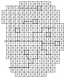
- The grid cells with Drain Code 3 drain to a local depression since no boundary or river link is found adjacent to a grid with the same drain code.
- The grid cells with Drain Code 1 or 2 drain to nearest river link located adjacent to a grid with the same drain code.
- The grid cells with drain code 0 do not contain drains and thus no drainage is produced.
- The grid cells with Drain Code -1 drains to local depression since no boundary is found adjacent to a grid with the same drain code.
- The grid cells with Drain Code -2 drains to nearest boundary grid with the same drain code.
The Pre-processed Drainage Reference System
During the preprocessing, each active drain cell is mapped to a recipient cell. Then, whenever drainage is generated in a cell, the drain water will always be moved to the same recipient cell. The drainage source-recipient reference system is displayed in the following two grids in the Pre-processed tab, under the Saturated Zone:
- Drain Codes - The value in the pre-processed Drain Codes map reflects the Option Distribution specified. For example, those cells with an Option Distribution equal to 1 (Drainage routed based on Drain Levels) will have a pre-processed Drain Code equal to 0, because the Drain Codes are not being used for those cells.
- Drainage to local depressions and boundary - This grid displays all the cells that drain to local depressions or to the outer boundaries. All drainage from cells with the same negative value are drained to the cell with the corresponding positive code. If there is no corresponding positive code, then that cell drains to the outer boundary, and the water is simply removed from the model. Cells with a delete value either do not generate drainage, or they drain to a river link.
- Drainage to river - This grid displays the river link number that the cell drains to. Adjacent to the river links, the cells are labeled with negative numbers to facilitate the interpretation of flow from cells to river links. Thus, in principle, all drainage from cells with the same positive code are drained to the cell with the corresponding negative code.
However, this is slightly too simple because the cells actually drain directly to the river links. In complex river systems, when the river branches are close together, you can easily have cells connected to multiple branches on different sides. In this case, the river link numbers along the river may not reflect the drainage-river link reference used in the model.
If you want to see the actual river links used in all cells, you can use the Extra Parameter, Canyon exchange option for deep narrow channels , to generate a table of all the river link-cell references in the PP_Print.log file.
Cells with a value of zero either do not generate drainage, or they drain to a the outer boundary or a local depression.
b. Saturated Zone drainage + Multi-cell Overland Flow
The topography is often used to define the SZ drainage network. Thus, a refined topography more accurately reflects the SZ drainage network.
The SZ drainage function uses a drain level and drain time constant. The drain level defines the depth at which the water starts to drain. Typically, this is set to some value below the topography to represent the depth of surface drainage features below the average topography. This depth should probably be much smaller if the topography is more finely defined in the sub-grid model. The drain time constant reflects the density of the drainage network. If there are a lot of drainage features in a cell then the time constant is higher and vice versa.
When using the multi-cell OL, the drainage system is updated in the sense that the drain level will be defined using the sub-scale topography information. The SZ drainage will include the following when using sub-scale:
- Multi-scale SZ drainage supported only in the PCG transient SZ solver
- Each sub-grid cell will have the same drain time constant defined by the value in the coarse grid.
- If the drain level is defined as an elevation, then all sub-grids will have the same drain level.
- If the drain level is defined by depth below the surface, then each sub- grid may have a unique drain level, since each sub-grid can have a different elevation. Each coarse grid cell has a water table that is common for all fine scale grids within the coarse grid.
- If the coarse cell water table is above the fine scale drain level, then drainage is calculated based on the drain time constant and the depth of water above the fine scale drain level.
- Total drainage in a coarse cell is the sum of all the fine scale drainage volumes.
- Drainage routing by levels will be determined by the coarse grid. However to make it more realistic with respect to the fine scale hydrology, the drainage routing by levels will be based on the lowest drain level in a coarse cell.
- Drainage to local depressions will be added to the SZ cell, and resultant ponding will then follow the multi-scale OL flow.
Disabling Multi-Cell Drainage
By default, if the multi-cell OL option is invoked, multi-cell drainage will be active. If you want to disable multi-cell drainage, perhaps for backwards compatability with older models, an Extra parameter option is availble to switch off multi-cell drainage:
| Parameter Name | Type | Value |
|---|---|---|
| disable multi-cell drainage | Boolean | On |
If this option is used, then the multi-cell drainage is switched off and the drainage will function using the groundwater level and drain level based on the course cells.
b. Internal validation of the drainage scheme
MIKE SHE performs an internal validation of the SZ drainage scheme. The following are used in connection with the sub-scale feature:
Drainage depths of zero
Zero depths are allowed and drainage depths above the topography are set to the topography. This allows drain levels at the ground surface. This check will be done on the coarse grid. That is, if the coarse grid drain level is above the coarse grid topography, a warning will be issued and all the sub-grid drain depths will be set to zero.
!!!Note Release 2011 In Release 2011 and prior releases, a drain level of zero turned off SZ drainage, and drain levels above topography were set to the topography (and turned off drainage). For backwards compatibility an Extra Parameter is available.
| Parameter Name | Type | Value |
|---|---|---|
| disable drains at or above ground | Boolean | On |
Drain levels vs River link elevations
There is an optional Extra Parameter check in the drainage routing by levels that checks on the river link bottom elevation.
| Parameter Name | Type | Value |
|---|---|---|
| check drain level against bed level | Boolean | On |
If the river link bottom elevation is higher than the drain level, the cell becomes a local depression. However, this will likely create a lot of local depressions beside the rivers.
When using the multi-grid OL option, the drainage in a coarse cell is controlled by the minimum drainage level in the cell. If one sub-grid cell has a drainage level below the bed level then the drainage in the entire cell is transferred to an internal depression.
!!!Note Release 2011 The check was originally added to prevent the "lifting" of drainage water up to a river link. However, in most cases, such lifting is probably unintentional. That is, the river bed has been poorly interpolated.
Prior to Release 2012, this was the default behaviour and the check above has been added for backwards compatibility.
There is a check on the drain levels below the bottom of the model. If the coarse grid drain level is below the coarse grid bottom of the model, then a warning will be printed and the drain level will be adjusted to the bottom of the model. In the sub-grids, you may have the situation where the sub-grid drain level is below the bottom of the model, but the average drain level is above. In this case, the sub-grid drain level will be the maximum elevation of the bottom of the model and the drain level. Meaning if the drain level of a sub-grid is below the bottom of the model, the drain level is adjusted to the maximum value of i) the bottom of the model and ii) the drainage elevation.