Particle Tracking Specification
1. Overview
| Particle Tracking Specification | |
|---|---|
| Conditions | if the Include Advection Dispersion (AD) Water Quality option selected in the Simulation Specification dialogue and the Random Walk Particle Tracking sub-option is specified |
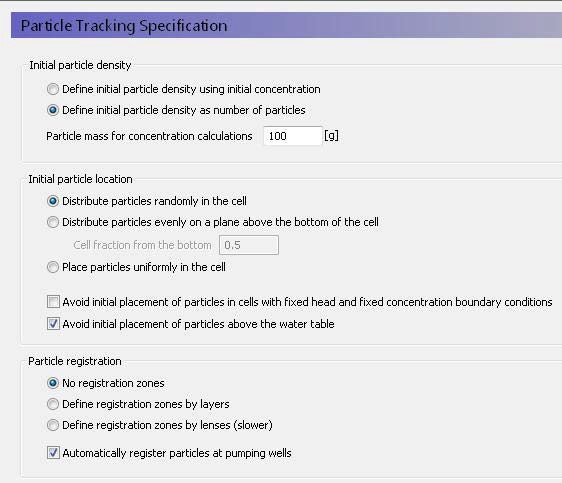
In the Particle Tracking Specification dialogue, you can select the initial density of particles, the initial location of the particles in the cells, and how the particles should be registered as the move through the saturated zone.
Initial particle density
The particle density relates the number of particles to a solute concentration. However, the initial number of particles can have a significant effect on simulation run time and output file size.
Define initial particle density as initial concentration
The initial concentration is defined for each SZ layer. See Initial (secondary) concentration. The number of particles in each cell is calculated by dividing the mass of solute in the cell by the particle mass specified in the text box below.
Define initial particle density as number of particles
If this option is selected, then an Initial number of particles per cell item is added to the data tree for each SZ layer.
Particle mass for concentration calculations
This mass is used for determining the initial number of particles if the first option above is selected. It is also used for converting the number of particles in a cell into a concentration during the simulation. A low mass per particle will yield more particles for the same concentration.
Initial particle location
The options for initial particle location determine the placement of the particles in each cell. If only a few particles are involved, the initial particle location can influence the results - especially if the cells are large.
A random distribution means that the particles may not be evenly distributed in every cell, but on average will be.
If the particles are evenly distributed on a plane, the particles are uniformly distributed on a plane parallel to the bottom of the cell. In this case, the optional fraction defines the location of the plane in the cell as a fraction of the cell thickness.
If the particles are evenly distributed in the cell, then the algorithm tries to distribute the particles evenly. This is relatively straight forward for regular numbers of particles, such as 4 or 5 particles, but more difficult for irregular numbers of particles, such as 11 particles.
Avoid initial placement in fixed head and concentration cells
Avoiding the initial placement in fixed head and fixed concentration cells, prevents some particles from being immediately extracted. (Default off)
Avoid initial placement above the water table
Avoiding the initial placement above the water table prevents particles being stuck right from the beginning of the simulation. If a particle is above the water table, then it will be immobile until the water table re-wets the location of the particle. This can happen when water tables are rising and falling. But an initial particle above the water table may never become active and you may have a situation where nearly all of the initial particles in the upper SZ layer remain immobile for the entire simulation. (Default on)
Particle registration
The random walk method can track thousands of particles during a simulation. Unlike path line analysis, the random walk method does not usually store all the resultant pathlines. Instead, it stores the starting point and the end location or exit location of the particle. If you want to know if the particle has passed through a particle zone or layer, then you can create a registration zone. If the particle passes through the registration zone, then this will be recorded.
You can define the registration zones by numerical layer, or you can define them be lenses similar to the way you define geologic lenses. In both cases additional items are added to the SZ data tree. Defining the registration codes by lense is slower, because the PT engine has to continually check to see if the cell is located in one or more registration zone.
Particle registration is by default automatically done when particles are removed at wells to make it easier to calculate well capture zones.
Related Items:
2. Particle Tracking Simulation Title
| Particle Tracking Simulation Title | |
|---|---|
| Conditions | if the Include Advection Dispersion (AD) Water Quality option selected in the Simulation Specification dialogue and the Random Walk Particle Tracking sub-option is selected. |
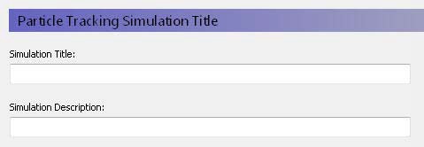
Title and Description
The Title and Description will be written to output files and appear on plots of the simulation results.
Related Items:
3. Particle Tracking Simulation Period
| Particle Tracking Simulation Period | |
|---|---|
| Conditions | if the Include Advection Dispersion (AD) Water Quality Simulation Specification dialogue and the Random Walk particle tracking option is selected |
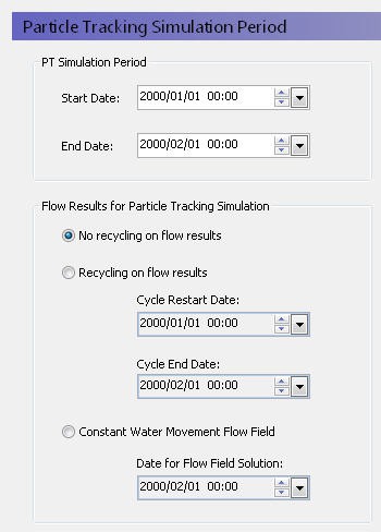
PT Simulation Period
The particle tracking simulation does not have to be the same length as the water movement simulation. The only restriction is that the start date for the particle tracking simulation must be within the water movement simulation.
Flow Results for Particle Tracking Simulation
A particle tracking simulation requires the cell-by-cell water fluxes calculated by the water movement simulation. However, the particle tracking simulation does not have to be the same period as the water movement simulation. Therefore, the user interface is flexible in how it will use water movement cell-by-cell flow data.
No recycling on results
In this case, the water quality simulation end date must also be within the water movement simulation period, which means that the water quality simulation cannot extend beyond the water movement simulation.
Recycling on flow results
In this case, the water quality simulation can be much longer than the water movement simulation, based on a repeated set of water movement results. The water quality simulation starts on the Start Date with the flow results from the Cycle Restart Date. When the water quality simulation period reaches the Cycle End Date, the WQ simulation will continue but the flow results will be restarted at the Cycle Restart Date.
If the recycle dates do not match one of the saved time steps, then the nearest saved time step is used.
For example, you may have a two-year water movement simulation, but you may want to simulate water quality for 10 years. To do this, you would specify the start and stop dates of the part of the water movement simulation that you want repeated. If you want to repeat the whole water movement simulation, then you would specify the beginning and end of the water movement simulation.
Constant water movement flow field
In this case, the nearest saved time step to this date will be used as a steady-state flow field for the transient water quality simulation.
Related Items:
4. Particle Tracking Control
| Particle Tracking Control | |
|---|---|
| Conditions | if the Include Advection Dispersion (AD) Water Quality option selected in the Simulation Specification dialogue and the Random Walk Particle Tracking sub-option is selected |
The particle tracking simulation is completely decoupled from the water movement simulation and like the water movement itself, the water quality time steps can be different in each of the overland flow, unsaturated flow and saturated flow.
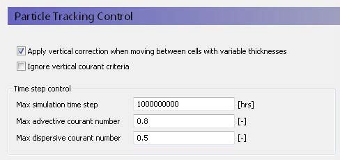
Apply vertical correction when moving between cells with variable thicknesses
This correction adjusts the vertical location of the particle, if the particle moves into a neighbouring cell with a different cell thickness. This prevents particles from being discharged to the ground surface when they move into an adjacent cell with a lower topography. By default, this option is on.
Ignore vertical courant criteria
With this option on, the calculation of the maximum time step length based on the courant criteria ignores the vertical velocities. In some cases, very small time steps may be required if the layers are thin, and the vertical velocities are high. However, such conditions often occur near particle sinks (e.g. wells and seepage faces) where detailed particle pathlines are not important.
Time step control
Maximum Simulation Time StepThis is the maximum user-specified time step allowed. The default value is very high so that the simulation runs by default with the highest possible time step. You might want to set this value to a short time interval, if you want the WQ time step to be uniform during the WQ simulation.
The courant number is a measure of the ratio of flow rate to grid size. For numerical stability, it is important that a dissolved solute does not travel too far in one time step. A courant number greater than 1.0 implies that a particle (solute) would move completely across or through a cell in a time step. The time step is reduced until all the time step criteria below are met.
Max. Advective Courant Number
The advective courant number represents the ratio of cell size to the time it would take a particle to move across a cell. This criterion is likely to be controlling if your flow velocities are high, or your dispersivity values are very low or zero. The default value is 0.8. If your actual time step is being controlled by this criterion, then you could increase it to make the simulation run faster. However, you will need to check to make sure the simulation has converged properly and that the mass balance is reasonable.
Max. Dispersive Courant Number
The dispersive courant number represents the ratio of the cell size to time it would take a particle to move across a cell due to dispersion. This criterion is likely to be controlling when the velocities are very slow and the dispersivity is non-zero. The default value is 0.5. If your actual time step is being controlled by this criterion, then you could increase it to make the simulation run faster.
However, you will need to check to make sure the simulation has converged properly and that the mass balance is reasonable.