Domain
1. Model Domain and Grid
| Model Domain and Grid | |
|---|---|
| dialogue Type | Special; Integer Grid Codes |
| EUM Data Units | Integer Grid Code |
| Valid Values | -1e-35, 1, 2 |
One of the first steps in your model development is to define the model area. On a catchment scale, the model boundary is typically a topographic divide, a groundwater divide or some combination of the two. In general, there are no constraints on the definition of the model boundaries. However, the model boundaries should be chosen carefully, keeping in mind the boundary conditions that will be used for both the surface water and groundwater components.
Any non-gridded data, such as point .shp files and xyz ASCII files are interpolated to the grid defined in this dialogue.
The grid defined in this dialogue is the primary grid. Other .dfs2 gridded data does not have to use the same grid. However, if another .dfs2 file uses a different grid then Real data is interpolated. If the two grids are coincident, that is the cells are the same size and the grids line up, then the data is bilinearly interpolated to the Model Grid. If the grids are not coincident, then the data is treated as if it were point values (i.e. the same as XYZ or .shp data). Integer Grid Code must use coincident grids, as it is impossible to interpolated integer values.
The model domain and grid can be rotated any angle measured clockwise from the x-axis.
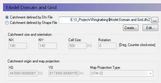
Using a dfs2 file
If you define your model domain using a dfs2 grid file, then you must define the cell values as follows:
- Grid cells outside of the model domain must be assigned a delete value - usually -1e-35.
- Grid cells inside the model domain must be assigned a value of 1.
- Grid cells on the model boundary must be assigned a value of 2.
This distinction between interior grid cells and boundary cells is to facilitate the definition of boundary conditions. For example, drainage flow can be routed to external boundaries but not to internal boundaries.
The catchment definition is displayed in the greyed-out text boxes but is not editable, since the catchment definition is part of the .dfs2 file format. If you want to change the cell size, origin, number of cells etc., you must change the .dfs2 file itself. For more information on editing and setting up the Model Domain and Grid see Conceptual geologic model for the finite difference approach.
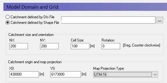
Using a shp file
It is much easier to define your Model Domain and Grid via an ArcView .shp file (i.e. a grid independent polygon). In this case, the definition of integer code values is taken care of automatically. Further, the definition of the grid (number of rows and columns, cell size and origin) can be easily adjusted.
Map projections
A projection is the way the earth’s curved surface is mapped onto a flat plane. The projection causes distortions as you move away from the center of the projection. One of the most common projection systems is the UTM system, which divides the earth into zones to minimize the distortion within a particular zone. Every place on earth has a UTM zone.
The earth is not a sphere, and the actual curvature varies locally across the globe. Thus, the other part of the projection is the assumed shape of the earth, which is defined as the Ellipsoid type. The ellipsoid used for the UTM system is WGS 84.
Thus, unless the projection and the ellipsoid are consistent between two maps, they will not overlap correctly. This is typically the reason if your model results do not appear to be located in the right place when you try to map them to Google Earth.
Map projections in MIKE SHE
Up until the 2009 Release, the only map projection allowed in MIKE SHE was NON-UTM. This is essentially the same as local grid coordinates. From the 2009 Release onwards, MIKE SHE uses the same map projection utilities as the rest of the MIKE Zero products, which is based on an installed library of standard world map projections.
You must define the map projection when you create a dfs2 file and this projection becomes part of the properties of the file. It can be changed in the Properties dialogue in the Grid Editor. Likewise, the map projection is a property of all shape files and can be changed in your GIS program.
Note
In the Model Domain and Grid, you must define the map projection. All of the rest of the dfs2 and shape files used in the model setup must use the same projection.
2. sub-catchment
| Sub-catchments | |
|---|---|
| Conditions | when either of the subcatchment-based methods for Overland Flow or Saturated Flow are selected in the Simulation Specification dialogue |
| dialogue Type | Integer Grid Codes with sub-dialogue data |
| EUM Data Units | Grid Code |
a. Sub-catchments
The Subcatchment item appears whenever you select one of the sub-catchment based methods - Simplified Overland Flow Routing or the Linear Reservoir Method for groundwater flow.
The subcatchment items are used to identify the hydrologic sub-watersheds in your model domain. For the Simplified Overland Flow Routing, the calculated overland flow in the Overland Flow Zones flows from one zone to the next within the Subcatchment. For the Linear Reservoir Method for groundwater flow, the calculated interflow is routed from one zone to the next within the Subcatchment.
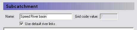
For each unique integer code in the main Subcatchment map view, an additional data item is added to the data tree. In each of these sub-items, there is only one additional variable - a checkbox for using the default river links.
Use default river links
In most cases you will link the simplified overland flow and the groundwater interflow to all of the river links found in the lowest topographic zone, or the lowest interflow zone in the subcatchment. However, in some cases you may want to link the flow to particular river links. For example, if your river network does not extend into the subcatchment, you can specify that the interflow discharges to a particular node or set of nodes in a nearby river network.
If you uncheck this checkbox, a sub-item will appear where you can specify the river branch and chainage to link the subcatchment to.
The river links for the baseflow zones are specified separately in the baseflow zone dialogues.
Related Items
b. River Links
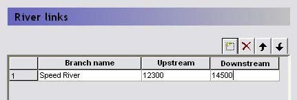
If you have unselected the Use default river links option in the Sub-catchments dialogue or in the Baseflow Reservoirs dialogue, then this dialogue will be added to the data tree. In this dialogue, you can specify the branch name to connect a subcatchment to, as well as the upstream and downstream chainage of the branch.
This dialogue is not intelligent, in the sense that it does not read the river net- work. You must type the branch name exactly as it appears in the river net- work file and specify valid chainages. If either the name or the chainages are invalid, then you will get an error during the model pre-processing stage.