Well editor
The Well Editor is the MIKE SHE tool for managing pumping wells. The data file for the well editor is independent of the numerical model. That is, the well file often contains all of the wells in the entire model region, including wells outside the model area. The preprocessing takes care of including only the relevant wells in the numerical model.
The dialogue for the Well Editor is divided into
- an Interactive Map of well locations
- a table of Well Locations
- a table of Well Filters for the current well
- a schematic Layers Display showing the relationship between the well screen, the current geologic model and the numerical layers.
The most common way to add data to the Well database is via ASCII import: Importing Data.
1. Interactive Map
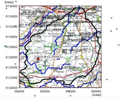
The interactive map displays all of the wells in the well file. Clicking on individual wells will select the corresponding item in the table of well locations. Similarly, selecting an item from the list will change the icon of the well on the map to a red square.
The overlays are automatically carried over from the model Setup Tab. You can’t add or modify overlays directly in the Well Editor. This must be down from the Setup Tab
Right clicking on the map, allows you to control the zoom and a number of other functions:
Grid - turns on/off a faint coordinate grid that changes with the zoom factor
Set new area coordinates - allows you to change the displayed area of the map
Text - turns on/off the display of the Well ID labels for the wells
Export Graphic - allows you to save the view to the clipboard, or a .bmp or wmf graphic file for importing into MSWord, for example.
2. Well Locations
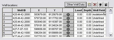
Well_ID - This is the user specified name of the well. The Well_ID cannot contain any spaces.
X, Y - These are the X and Y map coordinates of the well. EUM Data Units: Item geometry 2-dimensional
Level - The Level defines the maximum elevation shown on the profile view of the geologic layers, calculation layers, and screened intervals for the well. The topography is shown if the Level is less than the topography. EUM Data Units: Elevation
Depth - The Depth is defined from the Level. It defines the maximum depth shown on the graphical view displaying the profile view of the geologic layers, calculation layers, and screened intervals for the well. The bottom of the geologic layers is shown if the Level minus the Depth is higher than the bottom of the geologic layers. EUM Data Units: Depth below ground
Well Field - The Well Field item is used for filtering the displayed boreholes. The Mask item in the top menu bar uses the Well Field for it selection criteria. The Well Field item is also used to defined registration zones in the Random Walk Particle Tracking (PT) module. For more information, see Particle Tracking (PT), and Particle Tracking-Reference.
3. Well Filters
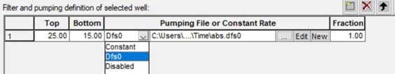
Top - This is the elevation of the top of the screen or open hole interval for the well (in the same units (ft, m, etc.) as specified in the EUM Database for item geometry 2-dimensional).
Bottom - The elevation of the bottom of the screen or open hole interval for the well (in same units (ft, m, etc.) as specified in the EUM Database for item geometry 2-dimensional).
Pumping File or Constant Rate - You have three choices here. Either a constant value for the pumping rate, name of the .dfs0 file with groundwater pumping data for the well (When using the Browse button, [...], to select the file, you will be given the option of specifying the Item number in the .dfs0 file.), or to disable pumping at this well.
Fraction - This is a multiplier for the groundwater pumping rate specified in the DFS0 File.
4. Layers Display
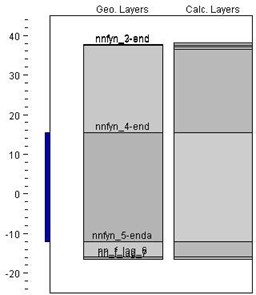
The Layer display section displays the location of all well screens assigned to the well. The Geo Layers column displays the geologic layers assigned in the Setup Tab for the well, and the Calc Layers is the numerical layers for the column of model cells in which the well is located.
Both the Geo Layers and the Calc Layers items require that the model has been successfully pre-processed. If you have not pre-processed the model yet, or if during the preprocessing an error occurred, then a warning message dialogue may appear saying that the model must be pre-processed first. If this happens, the Well Editor will function normally, but the Geo and Calc layers may not be shown.
5. Importing Data
In the top menu bar there is an Import menu, that allows you to import the following well data.
a. Zeus data (Adm and Lit)
The Zeus data is a specialized data format from the Geological Survey of Denmark and Greenland.
b. TAB delimited text file
The most common file format to import is a TAB delimited ASCII file, typically generated from Excel or a database program.
Several screened intervals can be specified for each well. Each screened interval should be imported on a different line. The line should include well properties, as well as screened properties.
Below is the format that each line in the ASCII file must follow:
Well_ID\>X\>Y\>Level\>Depth\>Well_Field\>Top\>Bottom\>Fraction\>dfs0_File\>dfs0_item
A simple example with three groundwater wells is given below.
CW1 7780.00 20331.00 0.00 0.00 CW 0. -60. 1. .\Time\ClassPumpage 1
CW2 8000.00 19000.00 0.00 0.00 CW -10. -50. 0.5 .\Time\ClassPumpage 3
CW3 7600.00 21300.00 0.00 0.00 CW 10. -60. 1. .\Time\ClassPumpage 2
The dfs0-item-number field is used to import Constant values or to disable the well as follows:
- if the dfs0_item value is positive, then the value is read as the dfs0 Item Number
- if the dfs0_item value is 0, then the dfs0_File value is read as the constant pumping rate
- if the dfs0_item is -1, then the pumping well is disabled.
Note
The import function does not allow spaces in the text fields. Also, you cannot import filter definitions as “disabled” or “fixed pumping rate”.