MIKE SHE versus MODFLOW
The MIKE SHE can be used to simulate all of the processes in the land phase of the hydrologic cycle, including overland flow, channel flow, groundwater flow in the unsaturated zone and saturated groundwater flow. MODFLOW, on the other hand, is restricted to simulating flow only in the saturated groundwater zone. Although many of the processes simulated in MIKE SHE are used in a similar way when simulating groundwater flow with MODFLOW, they are not actually “simulated” by MODFLOW.
Let’s take groundwater recharge as an example. MODFLOW allows you to include recharge as an upper boundary condition to the groundwater model, where recharge is defined as the amount of water reaching the groundwater table after accounting for evapotranspiration, surface runoff and changing storage in the unsaturated zone. In MODFLOW, the modeller has to account for these processes herself - usually by applying a constant rule-of-thumb fraction to the measured precipitation data. In most cases, the model results are very sensitive to this fraction and since the modeller has little data on this fraction, she will assume an initial value and use this parameter as a calibration parameter. Thus, she will adjust the amount of recharge during the calibration process until the measured groundwater levels match the calculated values.
However, the fraction of precipitation reaching the groundwater table is constant in neither space nor time. The actual amount of precipitation reaching the groundwater table depends strongly on the maximum rate of infiltration, which is a characteristic of the soil and will vary spatially over the model domain. Further, since the maximum rate occurs when the soil is saturated, different amounts of water will infiltrate during wet periods compared to dry periods. To complicate matters further, the length of the preceding dry period will determine the amount of available storage in the unsaturated zone. For example, if there has been a long dry summer period, then evapotranspiration may have created a large deficit of water in the unsaturated zone that must be satisfied before any water reaches the water table.
This example shows that infiltration of precipitation is a very dynamic process. It depends on a complex interaction between precipitation, unsaturated zone soil properties and the current soil moisture content, as well as vegetation properties.
In MIKE SHE, the saturated zone is only one component of an integrated groundwater/surface water model. The saturated zone interacts with all of the other components - overland flow, unsaturated flow, channel flow, and evapotranspiration.
In comparison, MODFLOW only simulates the saturated flow. All of the other components are either ignored (e.g. overland flow) or are simple boundary conditions for the saturated zone (e.g. evapotranspiration).
On the other hand, there are very few difference between the MIKE SHE Saturated Zone numerical engine and MODFLOW. In fact, they share the same PCG solver. The differences that are present are limited to differences in the discretisation and to some differences in the way boundary conditions are defined.
Setting up the saturated zone hydraulic model involves defining the:
- the geological model,
- the vertical numerical discretisation,
- the initial conditions, and
- the boundary conditions.
In the MIKE SHE GUI, the geological model and the vertical discretisation are essentially independent, while the initial conditions are defined as a property of the numerical layer. Similarly, subsurface boundary conditions are defined based on the numerical layers, while surface boundary conditions such as wells, drains and rivers (using MIKE 1D) are defined independently of the subsurface numerical layers.
The use of grid independent geology and boundary conditions provides a great deal of flexibility in the development of the saturated zone model. Thus the same geological model and many of the boundary conditions can be reused for different model discretisation and different model areas.
1 Importing a MODFLOW 96 or MODFLOW 2000 Model
A FORTRAN executable is automatically installed with MIKE SHE and located in the MIKE SHE bin directory. The program can be used to read a MODFLOW file set and extract the stationary distributed data to a set of point theme shape files. The shp files can then be used directly in MIKE SHE.
To extract data from a MODFLOW model, open a command prompt in the directory containing the input files. On the command prompt line, type
MShe_ModflowExtraction.exe file_name.pfs
The extraction will proceed silently - that is without any messages. To run the extraction with the messages, you need to use
MZLaunch file_name.pfs -e MShe_ModflowExtraction.exe
which will start the MZLaunch utility. The file_name.pfs variable is the input file for the MODFLOW extractor. The input file has the standard MIKEZero Pfs format. The input fields of the file are explained below. Lines starting with '//' are not read, but rather can be used as comment lines.
Table 34.1 is an example .pfs file for the MODFLOW data extractor program:
Table 34.1 MODFLOW Extraction.pfs file format and description
| Line item | Comment |
|---|---|
| [MIKESHE_ModflowExtraction] FileVersion = 3 | File version 3 is for Release 2009 and up |
| ModflowModel = 'MODFLOW-96' \\ModflowModel = 'MODFLOW-2000' | The ModflowModel variable should be changed to MODFLOW- 2000, if the MODFLOW model is a MODFLOW 2000 model. |
| NameFileName = |.\Airport5.nam| | The NameFileName is the name of the MODFLOW name file that contains all of the references to the other input files. The '|' around the name-file name and the path of the specified file name must be relative to the location of the pfs file. |
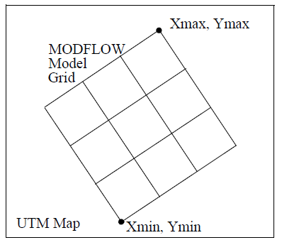
| XMin = 300 YMin = 400 XMax = 3032 YMax = 1132 |
The minimum and maximum (X,Y) coordinates are used to determine the exact spatial coordinates of the nodal points. XMin and YMin are the UTM coordinates of lower left MODFLOW corner. Xmax and Ymax are the UTM coordinates of the upper right MODFLOW corner. See figure next page. |
| TimeUnit = 'DAYS' | The TimeUnit is not currently used, but must be input. Valid values for TimeUnit are DAYS, HOURS, MINUTES and SECONDS. |
| LengthUnit = 'METER' | The LengthUnit is not currently used, but must be input. Valid values for LengthUnit are METER and FEET. |
| StartDate = 2005,1,1,0,0 | The start date and time of the MODFLOW simulation. Format: YYYY, MM, DD, HH, MM |
| WellExtraction = 1 | Extract well data to a dfs0 file. On: Flag = 1 Off: Flag = 0 |
| RechargeExtraction = 1 | Extract recharge input to a dfs2 file. On: Flag = 1 Off: Flag = 0 Note: only works with uniform MODFLOW grids. |
| HeadExtraction = 1 | Extract head results to a dfs2 file. On: Flag = 1 Off: Flag = 0 Note: only works with uniform MODFLOW grids |
| OutputFilePath = |.\MfExtractionDir\| | The output path is the directory location where the output files will be written to. |
| Shape_Or_Dfs2_Output = 1 | The parameter can have the values 1 or 2: 1 if shape file output is wanted, 2 if dfs2 output is wanted. |
| EndSect // MIKESHE_ModflowExtraction |
Note
MODFLOW does not have any internal unit checking. The units written in the MODFLOW file are only for display purposes. Also, the units that you define in your MODFLOW user interface may not be the same as those written to the MODFLOW files. So, you need to be careful of units and know what units the MODFLOW files are written in.
The MODFLOW name file has the usual MODFLOW format. However, you should
- Specify a new name for the LIST file not to overwrite the LIST file of an existing simulation, and
- Make copies of, or rename, all output files (lines starting with DATA). Existing result files might otherwise be overwritten during the execution of the extraction routine.
The coordinate information is the UTM coordinates of the lower left and upper right MODFLOW model corners - not the MODFLOW block-centered nodal coordinates.
These coordinates plus the DELR, DELC vectors from the MODFLOW files are used to defined the spatial location of the shape file and dfs2 output.
For a MODFLOW model, the extraction routine reads and outputs the following MODFLOW static parameters to a point theme shape file:
Top, Bot, Shead, Tran, Hy, Vcont, Sf1, and Sf2
Plus, it outputs the Specific storage, which is calculated as Sf1 divided by the layer thickness.
If the well output option is selected, a dfs0 file will be created. In this file, every cell in the MODFLOW file containing a well will have a seperate item in the dfs0 file.
If the recharge data and head results is selected, a dfs2 file will be created for each of these. However, the dfs2 format does not allow for variable grid spacing, which means that variable grid spacing will be ignored. The DELR and DELC for the first column and row will be used as the grid spacing in the dfs2 file. Thus, the recharge and head results output option is really only useful for MODFLOW models with a uniform grid spacing.
The extraction routine outputs point theme shape files -one file per data type - with one item for each extracted layer. The shape file names reflect the MODFLOW manual naming convention (Top.shp, Vcont.shp, etc.). The points represent the centre of each grid square. The model orientation is calculated from the user-specified coordinates of lower left (origin) and upper right corner of the model.
To use the MODFLOW data in MIKE SHE, select the Point/Line .shp option for the static variable. Then browse to the appropriate .shp file. The .shp file will contain one item for each model layer in the MODFLOW model. The appropriate item is selected in the file browse dialogue. Once the file has been assigned, MIKE SHE will automatically interpolate the data to the model grid.
Internal inactive zones
Currently, it is not possible to extract the inactive zones from the MODFLOW model and convert these to inactive cells in MIKE SHE. MODFLOW and MIKE SHE treat internal inactive zones quite differently. In MIKE SHE, the internal inactive zones are simply treated as cells with a very low hydraulic conductivity, whereas, MODFLOW ignores them in the solution. Furthermore, the extraction program only writes points to the .shp file for the active nodes. Thus, when it comes to the interpolation in MIKE SHE, the interpolation does not know about the inactive zone and interpolates through the inactive zone - there are simply no data points in the inactive zones.
Errors
The extraction utility is based on MODFLOW 96 and MODFLOW 2000 source code downloaded from the USGS MODFLOW website. The entire MODFLOW input routines were copied from these codes and used directly in the extraction utility.
If you encounter errors during the extraction, then you need to evaluate the log files generated to see where the error is.
- The extraction utility generates a .log file that includes error messages related to the errors in the .pfs input file.
- The .out file is a log file generated by the core MODFLOW input rou-tine that includes errors related to reading the MODFLOW files.
The most frequent source of errors is that the MODFLOW input files are not compatible with the standard USGS MODFLOW code. These errors show up in the .out file. The extraction process will only run if the entire set of MODFLOW files is completely compatible with MODFLOW. The easiest way to test your MODFLOW input files is to try to run the standard USGS MODFLOW executable from the command (DOS) line. The executable can be downloaded from the USGS website.